Current Transformers: A Tester Survival Guide
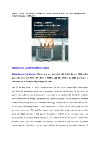
Current Transformers: A Tester Survival Guide. Bryan Shannon ABB Inc. Coral Springs, FL. Current Transformer: Equivalent Circuit. Current is Stepped Down [by primary and secondary windings]

Current Transformers: A Tester Survival Guide
E N D
Presentation Transcript
Current Transformers:A Tester Survival Guide Bryan Shannon ABB Inc. Coral Springs, FL
Current Transformer: Equivalent Circuit Current is Stepped Down [by primary and secondary windings] Exciting Impedance is the primary source of error. [By design Zo, Zi or Xm is very high to reduce Ie as much as possible] During Open CT Condition. A very high voltage is developed at CT terminals. [all secondary current flows through Xm]
Why Relay Accuracy CTs? • Under short circuit conditions, a small core that might be adequate for metering applications would “fill up” and be unable to carry the magnetic flux required to transform the current. • When this happens, the current transformer might be unable to induce a voltage high enough to maintain proper current flow in the secondary side. This could result in very serious errors. • Protection CTs require linearity in a wide range of currents
Calculated or Tested Accuracy • According to IEEE standards (C57.13), current transformers are given an accuracy rating with a “C” or a “T” • “C” indicates calculated accuracy and “T” indicates tested accuracy. • Using this system, current transformer with rating T100 would have to be tested to verify that it could sustain a voltage of 100 volts within normal accuracy limits. • “C” type are transformers which are constructed so that the effects of leakage fluxes on its performance are negligible, such as bushing current transformers with uniformly distributed windings.
Maximum Burden • Current transformers for relay applications are rated in the terms of the maximum secondary volts that can be induced on a twenty times short circuit rating – with error of current transformation limited to 10%. • For example, a current transformer rated 5 amperes secondary current, might be given a relay accuracy rating at 200 volts (C200). • This would indicate that the current transformer could sustain relaying accuracy – at 100 amps – as long as the secondary voltage IZ did not exceed 200 volts. • In this case, the maximum burden that could be used would be calculated as follows: Z (Burden)= E/I ( voltage rating / 20 times rated current of 5 amps) • = 200 volts / 100 amps = 2 ohms (Includes wiring and relays)
Benefits of Test Switches • Test switches provide a quick and safe means of testing relays. • Test switches are especially important wherever secondary current transformer circuits may need to be temporarily reconfigured to facilitate testing or where the relay must be temporarily disconnected from service. • Accidental opening of a CT secondary circuit can result in extremely high voltage and arcing, creating a dangerous hazard. • Test switches eliminate this possibility by diverting the secondary current to an alternate path before opening the connection to the relay. • This sequenced operation is inherent to the design of the current-shorting poles of a test switch.
Facilitate Simpler and Quicker Testing • Allows Access to Connections from Front of panel • Assures correct testing procedure sequence (Make before break of CTs) But, an Open CT can still occur.
Reasons for In-Service Testing • Competitive Electric Utility Market • More power wheeling/power needs • Control of supply chain resources • Requires reliable power delivery • Equipment availability • Deregulation of Electric Power • GENCO to TRANSCO separation • ISO activity requires metering • Need to use existing ITs • Bottom-line Focused • Billing and current swings • Must verify performance of ITs
Accidental Opening of current transformer due to: -Blown Fuse -Accidentally disconnected leads -Defective leads -Defective equipment -Incorrect Connections -Incorrect meter mode selected In Service Measurements – What could go wrong
Open CT • Current goes to zero until condition is restored • Every half cycle high voltage transients occur
Open Circuit Voltages • Because the open circuit voltage is limited by saturation of the core, the RMS value measured by a voltmeter may not appear to be dangerous. As the current cyclically passes through zero, the rate of change of flux at current zero is not limited by saturation, and is very high indeed. This induces extremely high peaks or pulses of voltage. Voltage transients up to 15Kv could be possible. • These high peaks of voltage may not register on the conventional voltmeter, but they can break down insulation and are dangerous to personnel. Current transformers are insulated to withstand, for emergency operation, secondary peak voltages up to 3500 volts
Current Dangers A value of 1500 ohms is commonly used as the resistance from arm to arm of the human body.
What Level is a Dangerous Voltage? OSHA says 50Vac is a hazard [1910.333(a)(1) and 1910.269(I)(1)] IEC (International Electrotechnical Commision): 30Vac Rms, 42Vac Peak, or 60Vdc
Consequences of Open CT • High voltage and shock hazard • Signal discontinuity to relay and controls could lead to incorrect operations and outages. • Potential magnetization of the CT leads to incorrect secondary output. This can cause error in readings, revenue metering calculations, incorrect operations long after the open CT condition is resolved.
Typical In-Service Testing Test Switch
Solution to existing problems Prevents Shock Hazards [Created by human error, and other causes] Prevent Blackouts [Created by human error, and other causes] Prevents CT erroneous reading (Avoid Magnetization) Test Switch Test Plug with Open CT Protection
How it works? • Detects rate of change of voltage and internal circuitry shorts CT • LED would indicate open CT condition present • Maintains signal to relay/IED • Eliminates possibility of false trip Test Switch Test Plug with Open CT Protection
Open CT Protection • Current signal integrity to relay maintained. [Prevents incorrect operations] • Voltage spikes limited to first occurrence • Voltage spikes limited to 35 Volts [Eliminates Shock Hazards]
Current waveform in Open CT with New Test Plug Minimizes distortion or signal discontinuity to protective devices, eliminating false trips and potential blackouts
User Exposure Comparison Maintains voltage to safe levels and reduces user exposure, thus increasing safety and eliminating equipment damage
Conclusions • Open CT conditions are a very likely event as more in-service testing is required • Open CT condition leads to Shock Hazard, Outages • Open CT could lead to incorrect readings long after condition is eliminated due to magnetization • Test Switches are recommended for installation with Current Transformers • Proposed test plug device eliminate risks due to operator error, incorrect equipment or risks arising due to normal testing practices and procedures.