Download
1 / 33
330 likes | 429 Vues
NanoMaker is an advanced e-beam lithography system that empowers SEMs/FIBs for nanostructuring. It offers a user-friendly interface, dynamic distortion correction, and exposure dose optimization. Developed by IMT RAS and Interface Ltd, it revolutionizes lithography resolution.

E N D
Ultimate 3D e-beam lithography for nano/micro-structuring with NanoMaker INTERFACE Ltd, Moscow IMT RAS, Chernogolovka, Moscow Region rev. 2015
Preview The NanoMaker is a powerful lithography system for electron and ion beam lithography using a commercial SEM, FIB or dual beam microscope. The NanoMaker solutions comprise modern Pattern Generator hardware and versatile data preparation software which allow both design and nanofabrication. It provides friendly graphic interface to create and design structures of nano-size as little as 10 nm based on e-beam lithography method for SEMs, make simulation of resist exposure, calculate exposure dose values/times in correlation with proximity effect correction for 2D/3D structures, compensate static distortion of e-beam deflecting system, significantly reduce total exposure time by reading and actively suppressing dynamic distortion of e-beam deflection. NanoMaker system is developed and launched as commercial product by Interface Ltd. NanoMaker system is a result of long and fruitful cooperation with a team of scientists based on IMT RAS, Chernogolovka, Moscow Region, Russia Ultimate 3D e-beam lithography for nano/micro-structuring with NanoMaker
Goals NanoMaker Lithography systems Families ofMicroscopes JEOL Zeiss FEI Hitachi Tescan Leo Focused Ion Beam and Dual Beam machines and others… The goal of NanoMaker is to achieve with a conventional microscope maximum resolution capacity in lithography mode. Practically it means to convert a standard lab electron microscope into a full-functionality e-beam lithography system by fitting software and hardware to control electron beam by compensating dynamic and static errors of deflection system. Just note that price for scanning electron microscope starts from USD 100,000.00 and price for full-functionality e-beam lithography system starts from USD 1,000,000.00 Cost starts from USD1,000,000 Cost starts from USD 100,000 Ultimate 3D e-beam lithography for nano/micro-structuring with NanoMaker
NanoMaker purpose NanoMakeris a unique complex, which facilitates Scanning Electron Microscopes to obtain the ultimate resolution and compensate inaccuracies of microscope characteristics. It is developed: • to create and design structures of various geometry forms and of nano-size as little as 10 nm to be exposed by e-beam lithography method • to work with 2D and 3D structures in resist, create multilevel structures • to overcome proximity effect appearing when micro- and nano- structures are exposed including 2D and 3D structures • to compensate static distortion of e-beam deflecting system by calculation methods • to significantly reduce total exposure time by measuring and actively, “on-the-fly”, compensating dynamic errors of e-beam deflection
NanoMaker purpose (continued) • to simulate results of resist development by matching exposure dose and time parameters to provide 100% of known-good output • to provide programmable control over cooperative movement of beam and stage, involving the blanking system as well • to provide compatibility with other graphic software systems to import and export other known formats for images and support various types of SEMs, FIBs, lithographs, etc. equipment • to support operations of scanning metrology microscopes and to work with fields, markers, video, etc. • to provide image acquisition and carry out processing for fields alignment and stitching • to work with large fields and provide seamless stitching of images Some of the features are unique and are not available in the market
NanoMaker hardware To provide capabilities of lithography systems NanoMaker consists of two main parts: Pattern Generator and Software modules. Pattern Generator is to control the exposure process by sending/receiving signals to/from microscope as it is sketched on the slide. Software modules are intended to solve a number of tasks depending on requirements to be mentioned further. Pattern Generator To control blanker To control e-beam position Image acquisition To control stage Ultimate 3D e-beam lithography for nano/micro-structuring with NanoMaker
NanoMaker hardware Pattern Generator Elli30 PCIe Hardware comprises two units: analogue unit and digital unit Analogue unit is a separate box with its own stabilized power supply unit. Digital and Analogue units are connected by two fiber optic cables to provide high speed noise protective data transfer. Digital unit is a PCIe Board Controller. • The Pattern Generator carries: • Two 16-bit Digital-to-Analogue Converters (50 MHz DACs) • One 8-bit Analogue-to-Digital Converter (ADC) • Beam Blanker On/Off switch (TTL output level) • Internal/External scan mode switch (TTL output level) • Output XY DACs and input ADC signals can be tuned for arbitrary intervals in ±10 V range.
NanoMaker software To provide capabilities of lithography system NanoMaker provides integrated development environment to create structures and design data NanoMakerprovides functions to control exposure and stage operations. NanoMaker provides functions to acquire marker’s images, to recognize them and to write structures under alignment control NanoMaker provides functions to compensate inaccuracies of microscope and improve lithography yield, i.e. : • compensates distortion and dynamic errors • calculates proximity effect correction • makes simulation and predicts the results of exposure
NanoMaker solutions . NanoMaker system can be supplied to the end user in various combinations: NanoMaker-Full to create and design structures of nano-size as little as 10 nm based on e-beam lithography method for SEMs, make simulation of resist exposure, calculate exposure dose values/times in correlation with proximity effect correction for 2D/3D structures, compensate static distortion of e-beam deflecting system, significantly reduce total exposure time by reading and actively suppressing dynamic distortion of e-beam deflection NanoMaker-Editoris fully featured graphical editor of lithographic structures with some limitations of export possibilities in unregistered version. Others functions can be simulated for training purposes. • NanoMaker-Writer – combination of the • Pattern Generator and software that allows to use a microscope • for lithography tasks. It is this stage when conversion to lithograph is done • and the best resolution to achieve proper lithography quality is possible. • The main functions of the Pattern Generator and software are: • to control important microscope parameters • to assign beam position (DAC), • to control stage position • to take image at the given location (ADC), • to switch on/off the e-beam blanker NanoMaker-Workbench– module to design 2D and 3D structures, solve a problem of proximity effect correction and to have output data in formats (GDSII, DFX, ELM…) acceptable by most brands of existing lithographs. The inverse transformation of data is also possible. It means that data released in mentioned above formats can be further corrected or re-designed and exported back in the same format. NanoMaker-Workbench allows to work in off-line mode (without being directly connected to a scanning microscope). NanoMaker complete system fully solves the task to convert scanning electronic microscope into e-beam lithograph NanoMaker-Full NanoMaker-Workbench NanoMaker-Writer NanoMaker-Editor
Alignment & Adjustment (Working with Video) Exposure (Writing ) -Design of (hierarchical / multilayered ) structure -Scan Field Alignment Using Test Pattern or Stage With Alignment&Compensation for Static/Dynamic deflection errors -Load / Save Graphical Data Base (GDB) files -Stage Adjustment to Test Pattern or to Scan Field -Import/Export GDS, DXF, ELM formats · -Image Acquisition SEM inaccuracies characterization for active compensation -Dynamic ( measurement of deflection system dynamic errors ) -Distortion ( measurement of deflrction system static errors ) Stage Control -Stage Driver Pattern Generator Interface Ltd. www.nanomaker.com NanoMakersoftware modules diagram Recommended Parameters Database Postprocessing Editor (Specialized 2D/3D CAD) · Negative, Union, Frame, Shrink, Erase, Stratification, Overlaps out… · · Proximity & Simulation Proximity Effect Correction Exposure & Development Simulation NanoMaker-Workbench NanoMaker-Writer
Practical implementations of modules OFFLINE MODE ONLINE MODE Import of structures NanoMaker-Writer NanoMaker-Workbench Data designing or redesigning *.DXF, *.CSF, *.GDS, *.TIF, *.BMP and holograms with complex topography up to 100 Mgb Export of data Pattern Generator Or transfer of structures Designing own structures
Unique features of NanoMaker In the market of similar software unites NanoMaker offers unique features: Proximity effect correction for 2D and 3D structures Simulation of resist development "Distortion compensation" - compensation of static distortions of deflection system Measurement and active compensation of dynamic distortions of deflection system and as a result – possibility to exposure without beam blanker Advantage features for hologram/kinoform applications
Proximity effect Proximity effect correction is especially important for closely packed, differently sized pattern elements. Though it is applicable to simple structures as well. The proximity effect becomes apparent in small enough areas when forward and backward scattering takes place in the substrate and leads to overexposure, thus resulting in breaking the accuracy of the structure. In the figure it is depicted an e-beam exposed to a chip. The chip consists of substrate covered with resist. Initially the e-beam was focused. However when it permeates both-way trough substrate and resist, electron scattering takes place. As a result radiation dose is disproportioned and final exposed area () is significantly more than it was initially (0) assigned. • This fact is depicted in the slide. • The resulting radiation dose redistribution in resist • is known as proximity function • and has the following values of parameters: • - fractions of micron, • 0 – hundredths of micron, • - microns. The fact is the more e-beam energy the more disproportion is. The value of disproportion is as well subject to parameters of substrate and resist. To the convenience of the users NanoMaker offers its own integral database of Recommended Parameters. It enables to fast match assignments of parameters. – e-beam width when leaving resist. It defines actually exposed area 0 – e-beam width when reaching resist – e-beam width when reaching substrate
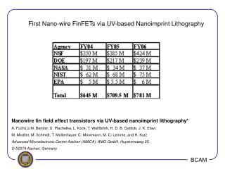
How Proximity effect works Z Simple exapmple to demonstarte the impact of proximity effect An elementary structure is shown. The total area is about 20 micrometers. The structure resembles field-effect transistor (FET). It consists of two rectangulars and has a line of 0.2 micrometers width. All gaps between elements are of the similar width (0.2 micrometers). The circuit is designed on Silicon chip with accelerating voltage of 25 Kilo electro Volt.
How Proximity effect impacts If proximity effect is not corrected then the result coud be depicted this way Simulation Photo of the exposed pattern The fact the top line is missing is due to insufficient radiation dose, contrary, excessive dose resulted in gaps vanishing between rectangular.
How proximity effect is corrected NanoMaker provides function to calculate the dose distribution along the area. Figure shows the areas depicted by isolines, which highlight the zones with uniform characteristics. In our case it means that each zone has ascending dose from 105% up to 125% against 100% initial dose .
Result of proximity effect correction After simulation shows satisfied results exposure is done 100% of known-good output
Simulation proximity effect and resist development One more unique feature of NanoMaker is possibility to output the lithography image simulated in the screen. It is possible to assign and alter various dose/time parameters and then follow it with preview in the screen as if resist development has taken place. In the preceding figures we can notice the coincidence with the experimental data obtained. This way simulation process effects in saving time and physical resources. We have to note that resulting accuracy of proximity effect correction is very much subject to accuracy of assigned parameters. Wrongly assigned, from accuracy point, parameters can even increase distortion effect. That is why NanoMaker maintains the database of Recommended Parameters for most common types of substrate.
Sample of proximity effect correction for 3D structure Presently the problem to create 3D structure with e-beam lithography, say for optical applications, comes into consideration more and more often Simulation ofeExposure dose. Iisolevels after correction Topographic expression of 3D structure An AFM image of a relief of transparent polymer DOE after copying from metal replica.
Example of creating 3D structure Kinoform optics Using 3D proximity correction and electron lithography, objectswith arbitrary 3D shape could be created with single exposure session.
Distortion compensation (static) One of the significant NanoMaker function is capability to compensate distortions, both static distortion of deflection system and dynamic distortion of e-beam long jump. The static distortions arise from electromagnetic lenses imperfection. Ideal shape of scanning Actual shape of canning NanoMaker provides with a function to measure the distortions of microscope operative field and store the values of deviation from pattern grid. These values are used for calculation of e-beam trajectory to meet the parameters of a given pattern grid.
Distortion compensation (dynamic) NanoMaker/Writer provides with one more absolutely unique feature to measure and carry out active compensation of dynamic distortions of deflection system. • NanoMaker solution • No blanker system is required when structure is written in one field • Compensate distortion by addressing to the trajectory resulting into ideal line • Common solution • Use blanker system • Wait till e-beam is settled at the point Result Waiting time usually exceeds pure exposure time several times Result Calculated exposure time is pure time of total exposure process
Example of distortion compensation The structure with long jump of e-beam No compensation With compensation
Alignment This function enables to make lithography of complex multi-layer structures. It enables: • acquire an image of existing lithography layers and recognize markers in automatic or semi-automatic mode • rotate, zoom and shift the image • align a new layer with existing objects of the image as per given markers • make exposure in a new coordinate frame
Alignment (example) Here we will demonstrate how it works on the samples prepared with the NanoMaker alignment function. In the figure shown gold contacts along with markers were done with optical lithography tools. With the help of NanoMaker the dimensions of gold contacts were measured, depicted and aligned with the given layers and whereupon they were pickled in hetero-structure on GaAs.
Alignment consequence First optical lithography With NanoMaker the dimensions of gold contacts were measured, depicted and aligned with the given layers and whereupon they were pickled in hetero-structure on GaAs. a) c) Placing metallic ferromagnetic material in the places marked by cross lines. d) b)
World market • Nearest competitors • The nearest competitors at the market are: • NPGS • Raith GmbH • We refer to the book: Micro-lithography, Micromachining and Microfabrication (ed. P Rai-Choudhury),Volume1: Microlithography, Section 2.5, written by M. McCord and M. Rooks. Web ref:http://www.cnf.cornell.edu/cnf_spie54.html
Resume NanoMaker – is a commercial product that can be customized as per customer’s requirements • The main purpose of NanoMaker system is to convert conventional • electron microscope into lithography system • Successfully defined and solved Proximity Effect Correction problem • for 2D and 3D structures that enables to fulfill designing and simulation • Unique functions are developed and implemented • Proximity effect correction for 3D structures • Static distortion compensation • Dynamic error correction
Photo Gallery (Cantilever needle) The examples of integration of NanoMaker into AFM are shown at the slides as possibility to grow up tips for cantilevers with high accuracy. Actually this is an unique technique which is used for industrial needs. The process is done in the standard work chamber. This technique is used in manufacturing probes/sondes and calibration standard for scanning sonde microscopy. NanoMaker enables to grow up the tip of a standard silicon cone tip and get tip with diameter of 100-200 nm and length up to unites of micrometer. Front Side view
Photo Gallery (Implementation for fun) Nature Materials - published the photo to illustrate macroscopic adhesive properties by showing a spider-man toy clinging with one of its hands to a horizontal glass plate. The toy (15 cm high; weighing 40 g) has its hand covered with the microfabricated gecko tape, which provides a 0.5 cm2 contact with the glass and a carrying capacity of >100 g. Imitation of gecko paws performed in lab with JEOL - 840
Photo Gallery (Nano World) The smallest map of the world. The width of line is 10 -20 nm
Contacts We thank you for your attention Please visit our site www.nanomaker.com Contact us at e-mail: sales@nanomaker.com