Download
1 / 10
160 likes | 456 Vues
ADC and DAC. Analog-to-Digital Conversion (ADC) and Digital-to-Analog Conversion (DAC) are the processes that allow digital computers to interact with these everyday signals. Digital information is different from its continuous counterpart in two important respects: it is

E N D
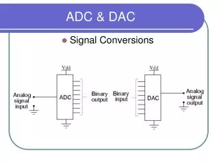
ADC and DAC Analog-to-Digital Conversion (ADC) and Digital-to-Analog Conversion (DAC) are the processes that allow digital computers to interact with these everyday signals. Digital information is different from its continuous counterpart in two important respects: it is sampled, and it is quantized http://www.dsptutor.freeuk.com/aliasing/AD102.html
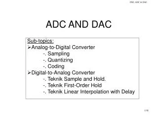
ADC Most DSP applications deal with analogue signals. the analogue signal has to be converted to digital form The analogue signal - a continuous variable defined with infinite precision - is converted to a discrete sequence of measured values which are represented digitally. Information is lost in converting from analogue to digital, due to: -inaccuracies in the measurement -uncertainty in timing -limits on the duration of the measuremen These effects are called quantisation errors
ADC Sample and Hold : The continuous analogue signal has to be held before it can be sampled. Otherwise, the signal would be changing during the measurement.
In the process of sampling the signal, some information is lost Due to Following 4 reasons:
Quantization Error • When the signal is converted to digital form, the precision is limited by the number of bits available. • The diagram shows an analogue signal which is then converted to a digital representation - in this case, with 8 bit precision. • The smoothly varying analogue signal can only be represented as a 'stepped' waveform due to the limited precision. • Sadly, the errors introduced by digitisation are both non linear and signal dependent.
Sampling frequency • We cannot see slow changes in the signal if we don't wait long enough. • In fact we must sample for long enough to detect not only low frequencies in the signal, but also small differences between frequencies. The length of time for which we are prepared to sample the signal determines our ability to resolve adjacent frequencies - the frequency resolution. • We must sample for at least one complete cycle of the lowest frequency we want to resolve. We must sample fast to avoid and for a long time to achieve a good frequency resolution. But sampling fast for a long time means we will have a lot of samples - and lots of samples means lots of computation, for which we generally don't have time. So we will have to compromise between resolving frequency components of the signal, and being able to see high frequencies.
Proper and improper sampling rate Aliasing due to low sampling rate
The sampling theorem • states that for a limited bandwidth signal with maximum frequency fmax, the sampling frequency fs must be greater than twice of the maximum frequency fmax, i.e., fs > 2· fmax • For the signal be uniquely reconstructed without aliasing. The 2·fmax is called the Nyquist sampling rate. The fmax, is called the Nyquist frequency. Do not confuse the above two values.
Aliasing • For example, the human ear can detect sound across the frequency range of 20 Hz to 20 kHz. According to the sampling theorem, one should sample sound signals at least at 40 kHz in order for the reconstructed sound signal to be acceptable to the human ear. Components higher than 20 kHz cannot be detected, but they can still pollute the sampled signal through aliasing. Therefore, frequency components above 20 kHz are removed from the sound signal before sampling by a band-pass or low-pass analog filter. Practically speaking, the sampling rate is typically set at 44 kHz (rather than 40 kHz) in order to avoid signal contamination from the filter rolloff.