Download
1 / 28
280 likes | 395 Vues
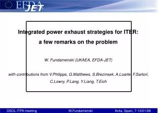
Integrated power exhaust strategies for ITER: a few remarks on the problem W. Fundamenski (UKAEA, EFDA-JET) with contributions from V.Philipps, G.Matthews, S.Brezinsek, A.Loarte, F.Sartori, C.Lowry, P.Lang, Y.Liang, T.Eich. Ignition vs. exhaust criteria for a reactor.

E N D
Integrated power exhaust strategies for ITER: a few remarks on the problem W. Fundamenski (UKAEA, EFDA-JET) with contributions from V.Philipps, G.Matthews, S.Brezinsek, A.Loarte, F.Sartori, C.Lowry, P.Lang, Y.Liang, T.Eich
Ignition vs. exhaust criteria for a reactor • In order for any exothermic reactor to operate in steady-state, • fresh fuel must be added at the rate at which it is consumed, • this fuel must be heated, ideally by the reactions themselves, • fuel must be confined, by whatever means are available, for sufficiently long to allow the exothermic processes to continue, • the energy and ash must be removed from the system at the rate at which they are created, • the impurities released from the reactor walls during this exhaust process must not inhibit the ignition (burn) of fuel, and • the reactor itself, primarily its walls, must not be damaged by all the exhaust processes. • Conditions (i)-(iii) represent ignition criteria, conditions (iv)-(vi) as exhaustcriteria. • Taken together these constitute the criteria of mutual compatibilitybetween the reaction processes and materials/components in an exothermic reactor • Since the latter provide the boundary conditions for the thermodynamic quantities, they effectively determine the maximum achievable energy gain for a given reactor design, i.e. a give combination of fuel and hardware.
Ignition vs. exhaust criteria for ITER • In order for ITER to operate in steady-state, • D & T must be added (NBI & pellet fuelling) at the rate at which they are consumed • D & T must be heated by RF, NBI and dominant a heating • D & T must be confined for sufficiently long to ensure Q = Pfus / Pheat = 10 • The (neutron, photon and plasma) power and He ash must be removed from the system at the rate at which they are created • the Be, C & W impurities released from the reactor walls must not inhibit the continued burn (Q=10) of D & T by either dilution and/or radiation, • The plasma facing components must not be damaged by the above processes. • e.g. joint requirement of partial detachment of both divertor legs (to reduce the inter-ELM heat loads below ~10 MW/m2), and ELM-mitigation (to reduce the ELM transient energy loads below ~1 MJ/m2). • (iv)-(vi) effectively impose the boundary conditions for the plasma density and temperature, and hence determine the maximum achievable Q in ITER, for a given set of internal and external hardware, i.e. TF, PF and control coils; PFCs; heating, fuelling, pumping and cooling systems, etc.
0.5 1.0 1.5 0.5 1.0 1.5 energy density / MJm-2 energy density / MJm-2 melting of the full tile surface(no droplet ejection) droplet ejectionandbridging of tiles after 50 shots significantPAN fibreerosionafter 50 shots PAN fibreerosion offlat surfacesafter 100 shot PAN fibreerosionafter 10 shots melting of tile edges negligibleerosion erosion startsat PFC corners negligibleerosion Transient heat load limits for ITER CFC W ITER adopted a value of 0.5 MJ/m2for the maximum allowed ELM energy load
Maximum permitted ELM size for ITER Using best estimates for divertor wetted area and in-out asymmetry, one finds DWELM = QELM x Sin x (1 + Pout/Pin) = 0.5 MJ/m2x 1.3 m2 x 1.5 ~ 1 MJ Assuming Wdia ~ 400 MJ and Wped / Wdia ~ 1/3, then DWELM/ Wped < 1% This requires a decrease in the ‘natural’ ELM size by a factor of ~ 20 Some caveats, e.g. the above assumes that the simulated ‘ELM’ pulse shape in the plasma gun is the same as the real ELM pulse in a tokamak 2 % 1%
AUG-Eich T.Eich Divertor heat loads due to ELMs Determination of divertor ELM power flux time dependence W. Fundamenski TRINITI plasma gun (from A.Loarte) JET-T. Eich more than 60% of DWELM,div arrives after qELM,divmax smaller DTsurfELM This inherent skewness could allow for a moderately larger ELM load (~ 30% higher)
Steady and transient wall loads on ITER Parallel (װ) ~1° Perpendicular (┴)
ELM control and effect on inter-ELM loads • On ITER, ELM size can be reduced by a combination of • pellet pacing • Necessary tool for deep (pedestal) plasma fuelling • external magnetic field perturbation (EFCC coils, RMP coils?, TF ripple) • 6x3 EFCC coils envision for error field correction • TF ripple in the range of 0.2-0.5 % • magnetic pacing (vertical kicks) • Not clear if suitable to ITER at present • impurity seeding (Type-III ELMs) • In the absence of C as radiator with Be/W mix, impurity seedind necessary for partial detachment • For all the above techniques it is imperative to determine • The maximum reduction in ELM size (increase of ELM frequency) • Associated reduction in confinement (H98) and fusion gain (Q) • Associated increase in inter-ELM heat loads (q_div, Te_div, Ti_div, q_lim) and any detrimental effects on divertor plasma detachment • Associated increase in core plasma pollution (Z_eff) • Synergistic effects • all the above processes (pellets/EFCCs/TF ripple/seeding) concurrent on ITER • Quantitative prediction beyond our abilities in the near future
ELM size reduction by pellet injection • Type-I ELM frequency can be increased by injection of small deuterium pellets, provided that pellet freq. > 1.5 natural ELM freq. (results from AUG) • Can the effects of plasma fuelling and ELM pacing be decoupled? • Can ELM pacing be demonstrated at N_GW ~ 0.75? fPel > 1.5 f0ELM
JET #70472 Bt = 1.85 T / Ip = 1.6 MA/ q95=4.0 PNBI (x10 MW) IEFCC (x16 kAt) 24 kAt ne,l(x1020m-2) core edge core Te (keV) edge Da (a.u) 12 14 16 18 20 Time (s) ELM size reduction by EFCC coils with n=2 Type-I ELM frequency can also be increased by introducing steady state n=1 or n=2 fields What is the change in confinement when the magnetic pump out is compensated by external fuelling? What is the effect in impurity seeded, highly radiative plasmas? • fELM↑~ 15 Hz ~ 40 Hz • DTe↓ ~ 650 eV ~ 250 eV • n_e ↓(pump-out) • T_e ↑(not fully understood) • H98 ↓ (~ 0-20 %)
Da kick FRFA current Wdia ne core (LID3) ne edge (LID4) Te edge ELM size reduction with vertical kicks Type-I ELM frequency can likewise be increased by fast changes (vertical kicks) to magnetic equilibrium Natural ELM frequency (~ 5 Hz) increased to ~ 10-25 Hz At freq. > ~35 Hz kicks do not always trigger an ELM Small reduction of Wdia and pedestal quantities: ne , Te Promising technique for ILW, in which case the ELM size need only be reduced by ~ 2-3 times 70426, 2MA 2.35T
Impurity seeded, highly radiative discharges Finally, ELM frequency can increased substantially (factor of ~ 10) by affecting a I-III transition, that is, by replacing Type-I by Type-III ELMs. Best pulse at 2.75MA/2.2T, high d • frad=0.75, Zeff ~ 1.5 – 2, N-seeded • H98(y,2) ~ 0.83 (~ 17% degradation) • bN ~ 1.9, n* reduced by ~ 2.5 • Both divertors detached ! At present the only scenario compatible with ITER requirements of 1% ELM energy loss + partial detachment, although at the penalty of confinement degradation of 15-20%, which yields Q ~ 4-5 @ 15 MA. Q=10 domain Zeff=1.7 Old results
Effect of TF ripple on ELMs ELM size, as well as H98, decrease with increasing TF ripple • For the same *ped, WELM/Wped decreases by factor of two when TF ripple increases from 0.1% to 1% • Change related to smaller conductive loss (Te/Teped), rather than convective loss (n/nped) • The reduction must less pronounced at higher density, i.e. close to N_GW ~ 1.
Some lessons from Be/W wall on JET The presence of Be on main wall (limiters, dump plate) and W in the divertor (especially W-coated CFC tiles) imposes new limits on plasma scenarios • Energy and power limits • Main chamber PSI, mainly during transients • Divertor steady state & transient loads • NBI shine-through • Special effects associated with RF power (ICRH and LH) Plasma compatibility issues 1. The risk of W contamination of (fuel dilution in) core plasma 2. Reduced edge and divertor radiation (in the absence of Carbon) 3. Hence, the need for impurity seeding to replace Carbon as the main radiating species
W-carbide W C Transient heat load limits for W-coatings on JET • Maximum coating test temperature in cyclic loading (200 pulses): 1600C • W-C carbide formation starts at about 1000C (exponential increase), “carbidisation” of the W layer should be avoided • W-C carbides have lower melting point, less ductility, and release C To have some margin for ELMs, Tmax should be below 1600C ( 1200C) Surface temperature is limiting in most cases (presently set by energy limits given by metallic base structures) Preliminary heat load tests in Judith simulator on 200m VPS (2000 Elms, 1 ms) found power limit of ~ 0.3 GW/m2(T. Hirai): ongoing analysis about failure mode at higher loads Recommend maximum transient heat load ~ 0.2 GW/m2
Maximum ELM size for W-coatings on JET Using best estimates for divertor wetted area and in-out asymmetry, one finds DWELM = QELM x Sin x (1 + Pout/Pin) ~ 0.2 GW/m2x 500 ms x 1 m2 x 1.5 ~150 kJ For typical JET stored energies of Wdia ~ 5 MJ and Wped / Wdia ~ 1/3, which translates into DWELM/ Wped < 9 % (less for larger Wdia). This requires a decrease in the ‘natural’ ELM size by a factor of ~ 2 9%
Maximum ELM size for W-coatings on JET Another possible methods of estimating maximum ELM size is based on maximum tile temperature rise, and is thus dependent on tile temperature. This gives somewhat higher limit for cold tiles (~ 250 kJ with safety margin).
Maximum T_e_div for W-coatings on JET • W erosion proceeds by physical sputtering with an ion energy threshold (for deuterium ions) of ~ 150 eV, or T_e_div ~ 150 / 5 eV ~ 30 eV. • Erosion of bulk W plate is not a critical issue for its life time • Erosion of W coatings, might be an issue, especially for the thinner coatings, which pose a high risk of gradually revealing the C substrate • Need to find an optimum between cooling the divertor plasma (< 30 eV) to reduce the erosion of W and introduction of seeding impurities which can themselves increase erosion (lower energy threshold for higher Z) • Need to aim for partial detachment (T_e_div < 5 eV) at both divertor legs !
Bulk Be ribbed Dump Plate ITER-like wall (ILW): Be wall Be limiter Surfaces moved forward 3cm (W- coated CFC recessed) Restraint ring protection Shinethrough Area 10μm W - coated CFC recessed Be coating of inconel
TZM spacers (coated with Al2O3) ZrO2 Tungsten (>99.95%) Inconel 625 W coatings optionalcopper inserts Inconel 706 Bulk W tile 8000 W- lamellas ITER-like wall (ILW): W/W-CFC divertor • W coatings: • 200 m VPS (Plansee) selected at first but more R&D show that thick VPS on CFC may not be reliable enough • change to 14 m thin Re-W multilayer coating is very likely (to be decided January 2008)
TZM spacers (coated with Al2O3) ZrO2 Tungsten (>99.95%) Inconel 625 optionalcopper inserts Inconel 706 Power and energy load limits for ILW 7.5 MW/m2 on JET CFC • Surface Temperature limits: • Steady state • Transient (ELMs) • Energy limit for metallic for substructures Elms Steady state
7.5 MW/m2 Similar thermal response for W, C and Be Start T = 220C Tmax<1200C forbidden Steady state heat load limits for ILW The limit on the steady state heat load determined by the maximum allowed coating temperature, heating power, radiation, SOL width and shot duration Maximum coating temperature 1600C 1200C for ELM window
A. Huber/R. Pitts ELM induced material loss on JET JET experiments at high Ip with ITER-like values of ELM size up to 1 MJ ELM affected area on JET ~ 1 m2. Hence, above increase occurs at ~ 0.7 MJ/m2, although the increase of radiation associated with ablation of surface layers, rather than bulk CFC
Main chamber heat loads due to ELMs ELM energy deposition at main chamber given by competition of parallel and perpendicular transport and filament size + detachment dynamics T. Eich/W. Fundamenski/R. Pitts Do larger ELM filaments travel faster? What is their spatial structure?