Download
1 / 23
240 likes | 274 Vues
Learn about grounding, fuses, circuit protectors, connectors, and more for proper maintenance of vehicle electrical components. Avoid electrical failures and ensure safe operation.

E N D
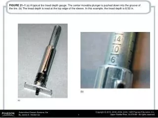
FIGURE 10-1 All lights and accessories ground to the body of the vehicle. Body ground wires such as this one are needed to conduct all of the current from these components back to the negative terminal of the battery. The body ground wire connects the body to the engine. Most battery negative cables attach to the engine.
FIGURE 10-2 Battery cables are designed to carry the heavy starter current and are therefore usually 4 gauge or larger wire. Auxiliary wiring for accessories and other electrical components is also connected to the positive battery cable on this vehicle. The plastic conduit (also called split-loom tubing) reduces the risk of damage.
FIGURE 10-4 Blade-type fuses can be tested through openings in the plastic at the top of the fuse.
FIGURE 10-5 Three sizes of blade-type fuses: mini on the left, standard or ATO type in the center, and maxi on the right.
FIGURE 10-6 A comparison of the various types of protective devices used in most vehicles.
FIGURE 10-7 To test a fuse, use a test light to check for power at the power side of the fuse. The ignition switch and lights may have to be on before some fuses receive power. If the fuse is good, the test light should light on both sides (power side and load side) of the fuse.
FIGURE 10-8 Typical blade circuit breaker fits into the same space as a blade fuse. If excessive current flows through the bimetallic strip, the strip bends and opens the contacts and stops current flow. When the circuit breaker cools, the contacts close again, completing the electrical circuit.
FIGURE 10-9 These electrical symbols are used to represent circuit breakers.
FIGURE 10-10 (a) Normal operation of a PTC circuit protector in a power window motor circuit. Note the many conducting paths. With normal current flow, the temperature of the PTC circuit protector remains normal. (b) When current exceeds the amperage rating of the PTC circuit protector, the polymer material that makes up the electronic circuit protector increases in resistance. As shown here, a high-resistance electrical path still exists even though the motor will stop operating as a result of the very low current flow through the very high resistance. The circuit protector will not reset or cool down until voltage is removed from the circuit.
FIGURE 10-11 PTC circuit protectors are used extensively in the power distribution center of this Chrysler vehicle.
FIGURE 10-12 Fusible links are usually located close to the battery and are usually attached to a junction block. Notice that they are only 6 to 9 in. long and feed more than one fuse from each fusible link.
FIGURE 10-13 (a) Demonstration showing the function of a fusible link by connecting a battery to each end with jumper cables. (b) After about 1 to 2 seconds, smoke starts to roll out from around the insulation. (c) After about 5 seconds, smoke fills the area as the wire inside finally melts and breaks (opens) the circuit. (d) The fusible link afterward .Notice that the special high-temperature insulation is unharmed even though the copper conductor has melted in half.
FIGURE 10-14 Some terminals have seals attached to help seal the electrical connections.
FIGURE 10-15 Separate a connector by opening the lock and pulling the two apart.
FIGURE 10-15 Separate a connector by opening the lock and pulling the two apart.
FIGURE 10-17 Use a small removal tool, sometimes called a pick, to release terminals from the connector.
FIGURE 10-18 Always use rosin-core solder for electrical or electronic soldering. Also, use small-diameter solder for small soldering irons. Use large-diameter solder only for large-diameter (large-gauge) wire and higher wattage soldering irons (guns).
FIGURE 10-20 Notice that to create a good crimp the open part of the terminal is placed in the jaws of the crimping tool toward the anvil or the W-shape part.
FIGURE 10-21 All hand-crimped slices or terminals should be soldered to be assured of a good electrical connection. Good fillets means that the solder should flow slightly from the clip and be smooth and shiny in appearance.
FIGURE 10-22 A butane torch especially designed for use on heat shrink applies heat without an open flame, which could cause damage.
FIGURE 10-23 A typical crimp-and-seal connector. This type of connector is first lightly crimped to retain the ends of the wires and then it is heated. The tubing shrinks around the wire splice and a thermoplastic glue melts on the inside to provide an effective weather-resistant seal.
FIGURE 10-24 The left side of this crimp-and-seal connector has been gently crimped and heated. Note how the connector has shrunk down around the wire. The heat has also released a thermal sealant that forms an effective environmental seal around the wire.