PMT Modular HV Supply Design Status
210 likes | 367 Vues
PMT Modular HV Supply Design Status. December 2003 Madison Instrumentation Workshop Nobuyoshi Kitamura UW-Madison. Outline. Documentation status Action Items status Design changes Design Verification Collaboration framework. Dec 03 Madison Workshop N. Kitamura UW-Madison.

PMT Modular HV Supply Design Status
E N D
Presentation Transcript
PMT Modular HV Supply Design Status December 2003 Madison Instrumentation Workshop Nobuyoshi Kitamura UW-Madison
Outline • Documentation status • Action Items status • Design changes • Design Verification • Collaboration framework Dec 03 Madison Workshop N. Kitamura UW-Madison
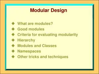
Modular Design Dec 03 Madison Workshop N. Kitamura UW-Madison
Documentation ERD for PMT Modular HV Power Supply HV-DOMMB Interface Requirements Procurement Documents HV Control Board PMT Base Board • Specification Control Drawing • Board mechanical drawing • Board envelope drawing • Schematic diagram • Toroidal transformer specification • Specification Control Drawing • Board mechanical drwaing • Board envelope drawing • Schematic diagram • Parts List • HV Generator Source Controlled Drawing http://amanda.wisc.edu/kitamura/HVM/HVM1.htm Dec 03 Madison Workshop N. Kitamura UW-Madison
Component Envelope Drawing Allows the maximum usage of the available volume for the vendors’ design. PSL 5549C104 Glen Gregerson (portion) http://amanda.wisc.edu/kitamura/HVM/5549104c_b.pdf Dec 03 Madison Workshop N. Kitamura UW-Madison
Documentation Status ERD—There are requirements to be refined / added (Action Items) All the documents need to be reorganized. Dec 03 Madison Workshop N. Kitamura UW-Madison
Action Items from May 03 PDR Dec 03 Madison Workshop N. Kitamura UW-Madison
PDR-1: HV Trade Study • “Active Base”—Integrated, unique, proprietary design. The vendor confidence is a major issue. • “Passive Base”—A number of potential vendors. Satisfactory performance of prototypes from current vendor. • Time / resource constraints precludes a “second-run” on Active Base. • More price and power consumption for Passive Base. No other downsides. • Focus on “Passive Base”. Pursue alternative vendors thru European channel. See summary on DocuShare:
PDR4: Coax negative margin Old 10kV per wire New http://amanda.wisc.edu/kitamura/HVM/toroid_spec.pdf Dec 03 Madison Workshop N. Kitamura UW-Madison
PDR-5: HV System Margins Determine the parts margins in the HV system for short term overvoltage acceptance testing and long term reliability/stability. • L, C, R and cabling are involved in the HV system. • Current design implementation (R, C) relies on vendor’s expertise. Dec 03 Madison Workshop N. Kitamura UW-Madison
PDR-6: Interface Noise Margin Reconcile the interface requirements between the PMT HV and the DOMMB including noise types and noise margin. • The DAC and ADC use a 3.3V logic (both level- and edge-sensitive). • The IDENT uses a 3.3V OneWire protocol (level-sensitive). • All the communication is dictated by the DOMMB. • No communication glitch has been encountered in the lab. Dec 03 Madison Workshop N. Kitamura UW-Madison
PDR-7: Voltage Monitor Range • Main point: • Is it necessary to monitor output voltage beyond the nominal maximum voltage (2047V)? • Proposed: Monitoring up to 2047V is sufficient. Voltage run-off beyond this limit may be detected by other means. Monitoring up to, e.g., 2100V adds cost and complexity. Dec 03 Madison Workshop N. Kitamura UW-Madison
PDR-8: Turn-on and transient power Specify the peak turn-on and other transient power requirements in addition to the steady state power. • The steady-state power is 300mW plus bleeder (40mW) max. • The load capacitance is known (~20 mF?). • The HV generator tolerates +15V (steady-state). • The active devices (ICs) are designed for 5V operation with absolute maximum of ???V. • The main board power supply has transient load limits, which must be compiled into this requirement. Dec 03 Madison Workshop N. Kitamura UW-Madison
PDR-9: Applicable PWB Specs Review the applicable PWB design specifications for minimum spacings. • Response submitted. • Reviewed IPC Generic Standard for trace spacings requirements. • The parameters are: • Voltage • hi/lo altitude • Overcoat or none • Conformal coat or none • The numbers in the previous versions of ERD are okay. Dec 03 Madison Workshop N. Kitamura UW-Madison
PDR-10: Output droop Specify the acceptable droop for a specific optical step function input. This requirement must be added to the ERD. Need to define the requirement based on physics requirements Lab work in progress with Chris Wendt. Preliminary measurements demonstrate that the droop never becomes prominent over the DOMMB digitizing time window. (Meeting the physics-based requirement appears to be a non-problem.) Dec 03 Madison Workshop N. Kitamura UW-Madison
PDR-11: Power-state management Create a state table for all conditions of power ON/OFF including transients vs. allowed conditions and actions such as cold start, warm start, warm-up, reboot delays, etc. A HV_DISABLE logic signal has been added to the interface. The use of this signal allows the HV system to be power cycled under more well-defined conditions. Dec 03 Madison Workshop N. Kitamura UW-Madison
PDR12: HV Monitoring and Adjustment by SW Create a requirement allocated to software for monitoring and adjusting PMT gain and other parameters due to drift. This is likely a multi-loop control problem based on HV Monitoring and Gain Measurement. Reading the HV ADC introduces noise in the analog signal chain. Thus HV Monitoring requires a special software coordination. Dec 03 Madison Workshop N. Kitamura UW-Madison
Design Changes DOMMB-HV Interface 20-pin 24-pin connector to accommodate HV_DISABLE. HV Control Board Same functionality with fewer components due to specification changes for HV Generator. Output cable changed from RG178 to RG403. PMT Base Board New toroidal transformer design Thru-hole components No conformal coating upon delivery Dec 03 Madison Workshop N. Kitamura UW-Madison
Design Verification • (A) Most items are obvious—verified by “inspection”: • Examples: “Is there a +5V power in the cable?” • (B) Digital and analog functions are tested straightforwardly by communicating with the DOMMB. • Examples: Read Board ID • (B) combined with manual measurement of analog output. • Examples: DAC code vs. HV output. • Items requiring special attention or setup. Some are in response to the action item work: • D1: Voltage stability • D2: Anode voltage ripple • D3: DC-current sourcing capability • D4: Pulse-current sourcing capability • D5: “droop” requirement test (optical response) • D6: Transformer pulse-response (not in the ERD (yet)) Dec 03 Madison Workshop N. Kitamura UW-Madison
Collaboration issue (Proposed / speculated) • Some of the Design Verification Tests will be split between Wisconsin and Wuppertal. • Wuppertal has proposed a component-level accelerated test suite (needs rework). • Long-term tests, including HV stability, may be suited for Wuppertal. • Wuppertal will identify an alternative vendor for the HV components. Dec 03 Madison Workshop N. Kitamura UW-Madison
Conclusion Dec 03 Madison Workshop N. Kitamura UW-Madison