Download
1 / 58
580 likes | 918 Vues
Let’s start with diode. Examples of Diode. The Basic Property of a Diode. Let’s have a demo. How does it work?. Block C Unit 1 Outline. Semiconductor materials (eg. silicon) Intrinsic and extrinsic semiconductors How a p-n junction works (basis of diodes) Large signal models

E N D
Let’s start with diode EE2301: Block C Unit 1
Examples of Diode EE2301: Block C Unit 1
The Basic Property of a Diode Let’s have a demo EE2301: Block C Unit 1
How does it work? EE2301: Block C Unit 1
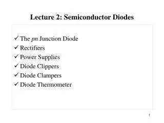
Block C Unit 1 Outline • Semiconductor materials (eg. silicon) • Intrinsic and extrinsic semiconductors • How a p-n junction works (basis of diodes) • Large signal models • Ideal diode model • Offset diode model • Finding the operating point • Application of diodes in rectification EE2301: Block C Unit 1
Semi-Conductors Electrical Materials Insulators Conductors Semiconductor Electronics - Unit 1: Diodes
Semiconductor Applications Integrated Circuit Semiconductor Electronics - Unit 1: Diodes
Semiconductor Applications TFT (Thin Film Transistor) Semiconductor Electronics - Unit 1: Diodes
Intrinsic Semiconductor Si Si Si Si Covalent Bonds Semiconductor Electronics - Unit 1: Diodes
Silicon Crystal Lattice In 3-D, this looks like: Number atoms per m3: ~ 1028 Semiconductor Electronics - Unit 1: Diodes
Growing Silicon We can grow very pure silicon Semiconductor Electronics - Unit 1: Diodes
Conduction Semiconductor Electronics - Unit 1: Diodes
Currents in Semiconductor Source: http://hyperphysics.phy-astr.gsu.edu/HBASE/solids/intrin.html Semiconductor Electronics - Unit 1: Diodes
Carrier Concentration The number of free electrons available for a given material is called the intrinsicconcentrationni. For example, at room temperature, silicon has: ni = 1.5 x 10¹⁶ electrons/m3 1 free electron in about every 1012 atoms Semiconductor Electronics - Unit 1: Diodes
Doping: n-type 1 Si atom substituted by 1 P atom Si Si Si P has 5 valence electrons (1 electron more) - P Si Si 1 free electron created Electrically neutral Semiconductor Electronics - Unit 1: Diodes
Doping: p-type 1 Si atom substituted by 1 B atom Si Si Si B has 3 valence electrons (1 electron short) + B Si Si 1 hole created Electrically neutral Semiconductor Electronics - Unit 1: Diodes
p-n Junction Semiconductor Electronics - Unit 1: Diodes
+ + + + + + + + + + + + + + + + + + + + + + - - - - - - - - - - - - - - - - - - - - - - Diode Physics - - - + + + - - - + + + - - - + + + - + - + - + + - Semiconductor Electronics - Unit 1: Diodes
+ + + + + + + + + + + + + + + + + + + + - - - - - - - - - - - - - - - - - - - - Diode Physics - - - + + + - - - + + + - - - + + + - - - - - + + + + + - - - - - + + + + + - - - - - + + + + + - + Website: http://www-g.eng.cam.ac.uk/mmg/teaching/linearcircuits/diode.html Semiconductor Electronics - Unit 1: Diodes
Biasing and Conventions vD: Voltage of P (anode) relative to N (cathode) iD: Current flowing from anode to cathode EE2301: Block C Unit 1
Diode Diode equation: ID = I0 [exp(eVD/kT) - 1] Diode begins to conduct a significant amount of current: Voltage Vγ is typically around 0.7V EE2301: Block C Unit 1
Diode Symbol and Operation Forward-biased Current (Large) Reverse-biased Current (~Zero) iD - + + - Forward Biased: Diode conducts Reverse Biased: Little or no current EE2301: Block C Unit 1
Real diode circuits + VD - ID To find VL where VT and RT are known, First apply KVL around the loop: VT = VD + RTID Then use the diode equation: ID = I0 [exp(eVD/kT) - 1] At T = 300K, kT/e = 25mV + VL- +- VT RT We then need to solve these two simultaneous equations, which is not trivial. One alternative is to use the graphical method to find the value of ID and VD. EE2301: Block C Unit 1
Graphical method Equation from KVL Operating point is where the load line & I-V curve of the diode intersect EE2301: Block C Unit 1
Diode circuit models • Simplify analysis of diode circuits which can be otherwise difficult • Large-signal models: describe device behavior in the presence of relatively large voltages & currents • Ideal diode model • Off-set diode mode EE2301: Block C Unit 1
Ideal diode model In other words, diode is treated like a switch here vD > 0: Short circuit vD < 0: Open circuit EE2301: Block C Unit 1
Ideal diode model Circuit assuming that the ideal diode does not conduct Circuit containing ideal diode Circuit assuming that the ideal diode conducts EE2301: Block C Unit 1
Ideal diode example 1 Problems 9.7 and 9.8 Determine whether the diode is conducting or not. Assume diode is ideal Repeat for Vi = 12V and VB = 15V EE2301: Block C Unit 1
Ideal diode example 1 solution Option 1: Assume diode is conducting and find the diode current direction Outcome 1: If diode current flows from anode to cathode, the assumption is true Diode is forward biased Outcome 2: If diode current flows from cathode to anode, the assumption is false Diode is reverse biased Option 2: Assume diode is not conducting and find the voltage drop across it Outcome 1: If voltage drops from cathode to anode, then the assumption is true Diode is reverse biased Outcome 2: If voltage drops from anode to cathode, then the assumption is false Diode is forward biased This slide is meant to be blank EE2301: Block C Unit 1
Ideal diode example 1 solution • Assume diode is conducting • Forward-bias diode current (ie anode to cathode) • = (10 - 12) / (5 + 10) = -2/15 A • Assumption was wrong • Diode is in reverse bias • Assume diode is not-conducting • Reverse-bias voltage (ie cathode referenced to anode) • = 12 - 10 = 2V • Assumption was correct • Diode is in reverse bias This slide is meant to be blank EE2301: Block C Unit 1
Ideal diode example 1 solution • Assume diode is conducting • Forward-bias diode current (ie anode to cathode) • = (15 - 12) / (5 + 10) = 1/5 A • Assumption was correct • Diode is in forward bias • Assume diode is not-conducting • Reverse-bias voltage (ie cathode referenced to anode) • = 12 - 15 = -3V • Assumption was incorrect • Diode is in forward bias This slide is meant to be blank EE2301: Block C Unit 1
Ideal diode example 2 Problem 9.14 Find the range of Vin for which D1 is forward-biased. Assume diode is ideal The diode is ON as long as forward bias voltage is positive Now, minimum vin for vD to be positive = 2V EE2301: Block C Unit 1
Offset diode model EE2301: Block C Unit 1
Offset model example Problem 9.19 The diode in this circuit requires a minimum current of 1 mA to be above the knee of its characteristic. Use Vγ = 0.7V What should be the value of R to establish 5 mA in the circuit? With the above value of R, what is the minimum value of E required to maintain a current above the knee EE2301: Block C Unit 1
Offset model example solution ID = (E - VD)/R When the diode is conducting, VD = Vγ ID = (5 - 0.7)/R We can observe that as R increases, ID will decrease To maintain a minimum current of 5mA, Rmax = 4.3/5 = 860 Ω Minimum E required to keep current above the knee (1mA), Emin = (10-3 * 860) + 0.7 = 1.56V This slide is meant to be blank EE2301: Block C Unit 1
Rectification: from AC to DC One common application of diodes is rectification. In rectification, an AC sinusoidal source is converted to a unidirectional output which is further filtered and regulated to give a steady DC output. Supply is AC DC required EE2301: Block C Unit 1
Rectifier with regulator diagram Rectifier Regulator Filter Bi-directional input Steady DC output Unidirectional output We will look at two types of rectifiers and apply the large signal models in our analysis: 1) Half wave rectifier 2) Full wave rectifier EE2301: Block C Unit 1
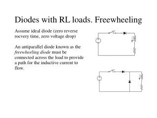
Half-Wave Rectifier ~ ~ VS VS RL RL We can see that the circuit conducts for only half a cycle VL VS • On the positive cycle • Diode is forward biased • Diode conducts • VL will follow VS • On the negative cycle • Diode is reverse biased • Diode does not conduct • VL will remain at zero EE2301: Block C Unit 1
Average voltage in a HW Rectifier 2nd half of period 1st half of period NB: This is equal to the DC term of the Fourier series EE2301: Block C Unit 1
Full-Wave Rectifier • Also known as BRIDGE rectifier • Comprises 2 sets of diode pairs • Each pair conducts in turn on each half-cycle ~ VS EE2301: Block C Unit 1
Full-Wave Rectifier EE2301: Block C Unit 1
Full-Wave Rectifier Repeats for every half a period: Integrate through half a period Half a period T/2 – time π – phase NB: This is equal to the DC term of the Fourier series EE2301: Block C Unit 1
Full-Wave Rectifier (offset) VD-on (only one diode is on) 2VD-on (two diodes are on) With ideal diodes With offset diodes EE2301: Block C Unit 1
Ripple filter Anti-ripple filter is used to smoothen out the rectifier output Charging Discharging EE2301: Block C Unit 1
Ripple filter Approximation: abrupt change in the voltage From transient analysis: VMexp(-t/RC) VL Ripple voltage Vr = VM - VL min EE2301: Block C Unit 1
Ripple filter example Problem 9.40 Find the turns ratio of the transformer and the value of C given that: IL = 60mA, VL = 5V, Vr = 5%, Vline = 170cos(ωt) V, ω = 377rad/s Diodes are fabricated from silicon, Vγ = 0.7V EE2301: Block C Unit 1
Ripple filter example solution a) TURNS RATIO: To find the turns ratio, we need to find VS1 and VS2 EE2301: Block C Unit 1
Ripple filter example solution But VM is not equal to VS1 due to voltage drop across diodes So we now apply KVL on the secondary coil side: VS1 - VD - VM = 0 VS1 = 5.825 V (VD = 0.7V) Turns ratio, n = Vline / VS1 ~ 29 EE2301: Block C Unit 1
Ripple filter example solution b) Value of C: Need to find the RC time constant associated with the ripple RL = VL/IL = 83.3 Ω We know it decays by VMexp(-t/RC), we now just need to know how long this lasts (t2) VL-min = - VSOcos(ωt2) - VD-on vso is negative at this point EE2301: Block C Unit 1
Ripple filter example solution t2 = (1/ω) cos-1{-(VL-min + VD-on)/VSO} = 7.533 ms VL-min = VM exp(-t2/RLC) Decaying exponential: VL-min = - VSOcos(ωt2) - VD-on 2nd half of the sinusoid EE2301: Block C Unit 1