1. Model common control system components.
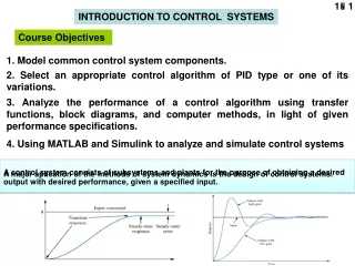
INTRODUCTION TO CONTROL SYSTEMS. Course Objectives. 1. Model common control system components. 2. Select an appropriate control algorithm of PID type or one of its variations.


1. Model common control system components.
E N D
Presentation Transcript
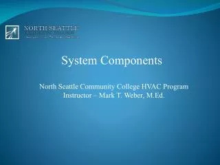
INTRODUCTION TO CONTROL SYSTEMS Course Objectives 1. Model common control system components. 2. Select an appropriate control algorithm of PID type or one of its variations. 3. Analyze the performance of a control algorithm using transfer functions, block diagrams, and computer methods, in light of given performance specifications. 4. Using MATLAB and Simulink to analyze and simulate control systems A control system consists of subsystems and plants for the purpose of obtaining a desired output with desired performance, given a specified input. A major aplication of the methods of system dynamics is the design of control systems.
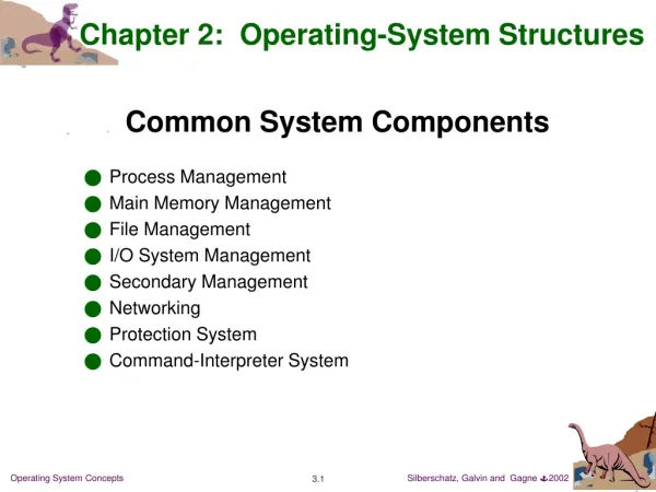
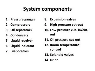
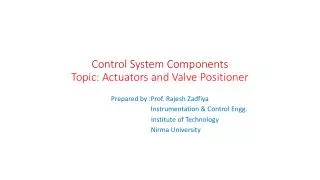
Basic Components of a Control System • Objectives of control (Inputs) • Control system components (Controller, plant, actuator, sensor,…) • Results (Outputs) Automobile : Sensors (Displacement,speed,force,pressure,temperature, fluid flow, fluid level voltage, current). Actuators (DC motors, step motors, pumps, heat sources) Home Heating System : Sensors (Temperature, pressure, fluid flow). Actuators (Motors, pumps, heat sources) Robot : Sensors (Optical image, displacement, speed,force, torque, pressure voltage, current). Actuators (AC motors, DC motors, step motors, hydroulic actuators) Control systems Open-loop control sytems Closed-loop control sytems
Plant Plant Actuator Actuator Open Loop Control Systems: u v Input Output Sensitive to changing in parameters and disturbance. Closed Loop Control Systems: (Feedback Systems) Control (Actuation) Signal Sensing signal Disturbance Error u Reference + Output + + Controller Sensor - Error signal= Reference – Sensing signal
Heater Examples of Control System Applications Heater Furnace Sensor Annealing Furnace Servo motors Washing machine Robots Home heating system Cruise control
Home Heating Control System : Reference temp. Controller (Thermostat) Temperature Sensor : Measured temp. : Disturbance Control signal (heat transfer: door, window, wall, etc.) Fuel flow Heater Valve Error Status Control action Open valve Cold Hot Close valve Open Loop: Closed Loop: + Plant Temp. Sensor + + Controlller (Thermostat) Valve -
Cruise Control System Usage in 1990’s Driver comfort Save fuel Road conditions Error signal Measured speed signal Fuel flow Vehicle speed Control signal Reference + + Motor and Powertrain system Speed Sensor Actuator(Valf) + Controller Speed -
a) Mathematical model (Cruise Control System) : Fp: Pushing force (from engine) Fd: Distrubance (wind, gravity, enviromental factors, etc.) b) Closed loop control:
Control Aplications with Industrial Robots Inverted pendulum control Ball grabber
x Z
V e x VrControl Input fd:Disturbance Vs:Response
Free Body Diagrams: External forces, Joint forces, The Law of Action-Reaction
V e P (Proportional) control:
No Disturbance Kp Steady State Error Disturbance Fd=10N Kp constant, Steady State Error Disturbance Fd=10N Kp constant, Ki Steady State Error 0 No Disturbance Steady State Error Disturbance Fd=10N Kp constant, Ki constant, Kd Overshoot Vibrations
clc;clear;close all m=100; c=4; k=4000; Ka=3e-2; Ks=100; Kp=10;Ki=5;Kd=0;kz=0.01; kfd=10; %Kp=0 to get open loop response. nho=Ka*Ks*[c,k];dho=[m,c,k];nhdo=Ks; nc=[Kd,Kp,Ki];dc=[1 0]; if Ki==0; nc=[Kd Kp]; dc=1; end %% n1=1; d1=[m,c,k]; nh=Ka*Ks*conv(nc,[c,k]);nhd=Ks*dc; dh=conv(dc,d1);dh=polyadd(dh,nh); sys1=tf(nh,dh); sys2=tf(nhd,dh); syso=tf(nho,dho); sysd=tf(nhdo,dho); p=roots(dh);p0=p(1);cksi dt=0.001;tson=50; t=0:dt:tson; [c1,t]=step(sys1,t); [c2,t]=step(sys2,t); c=kz*c1+kfd*c2; co=step(syso,t);cd=step(sysd,t); co=kz*co+kfd*cd; if Kp==0; plot(t,co) %Open Loop Response else plot(t,c) %Closed Loop Response end