Download
1 / 9
90 likes | 130 Vues
Learn about the Digital to Analog Converters (DAC) used to convert digital signals to analog outputs, including types like Weighted-Resistor DAC and R-2R Ladder DAC, along with examples and designs. Understand principles and applications in electronics.

E N D
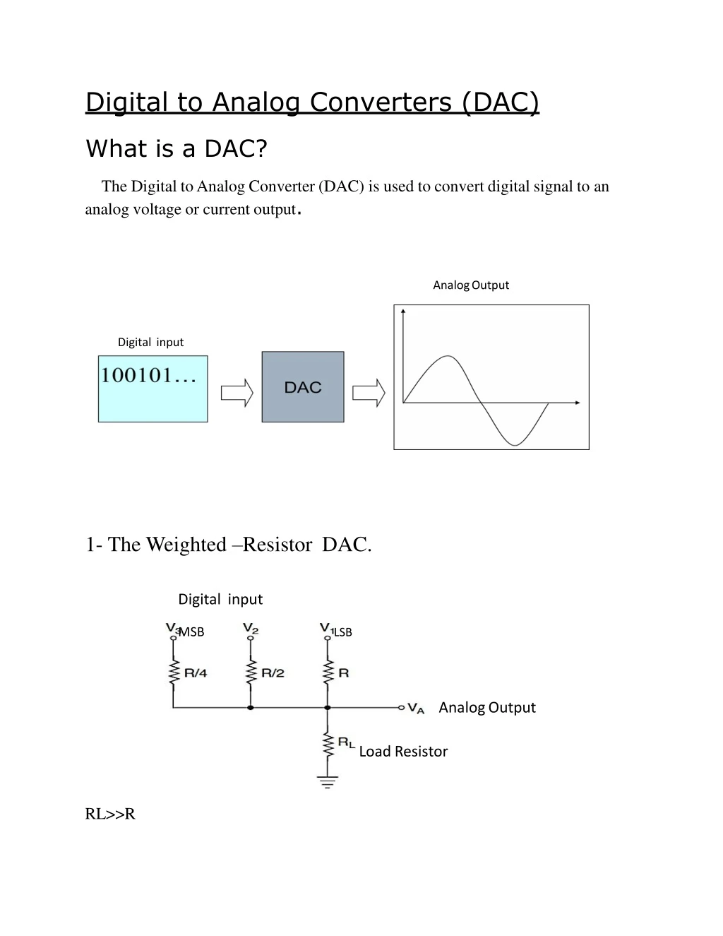
Digital to Analog Converters(DAC) What is aDAC? The Digital to Analog Converter (DAC) is used to convert digital signal to an analog voltage or currentoutput. AnalogOutput Digitalinput 1- The Weighted –ResistorDAC. Digitalinput MSB LSB AnalogOutput LoadResistor RL>>R
99 The output voltage, VA, may be found using Millman'stheorem: Assume that: Logic "0" =0 V Logic "1"=+7V * VIH = VINHigh ao2o + a121 + ⋯ .+an−12n−1 Vo= ∗VinH 2n −1
100 Example 1:For a 4 input resistive divider (0=0V, 1=10V)find The full-scale outputvoltage. The output voltage change due to theLSB. The analog output voltage for a digital input of1011. Sol.: The max. Output voltage occurs when all the input (1111) at +10V (ignoring the effects ofRL). 0→15 the LSB must be equal to 1/15 of the full scale output. Therefore the change in the output voltage due to the LSBis +10 * 1/15 =+2/3V Using Millman's theorem, the output voltage for a digital input of 1011is: ao20+ a121+⋯+an−12n−1 Vo= × V H in 2n−1 1 ∗ 2o+ 1 ∗ 21+0 ∗ 22+1∗ 23 Vo= ×10 24−1 Vo =110 / 15 =7.33v
H.W: For a five-bit resistive divider,determine: a) The weight assigned to the LSB and also the second and the thirdLSB. The change in output voltage due to a change in theLSB. The output voltage for a digital input of 10110. Assume 0= 0V and 1= +10V. 101 2- The R-2R LadderDAC. DigitalInput AnalogOutput Assume that Logic "0" = 0v Logic "1" =10v o 1 n−1 Vo = ao2 +a12 +⋯+an−12 ∗VIH 2n
3- Feedback AmplifierDAC. Vo = − F.BResistor Ri Vref 102 For R1 = R, R2 = 2R, R3 = 4R, R4 = 8R, Ri =R [a1R+a2(2R)+a3(4R)+a4(8R)] V =V o ref R Vo = Vref(a1 + 2a2 + 4a3 +8a4) Multiplying DAC[MDAC] 0Switchisclosed a ={ } i 1Switchisopen 4- Simple D/A converter using op-amp summingamplifier.
103 Example2: So we shall assume that 0 = 0V and 1 =8V When input DCBA = 0000, then putting these value in above equation (1) weget: When digital input of the circuit DCBA = 0001, then putting these value in above equation (1) we get:
When digital input of the circuit DCBA = 0010, then putting these value in above equation (1) we get : Resolution: The number of bits making up the input data word that will ultimately determine the output step voltage as a percentage of full-scale output voltage. Example 3: Calculate the resolution of an 8-bitDAC. Solution: Resolution = 8 bits Percentage resolution= 104 Design of D/A Converter: To complete the design of the D/A converter, there must be a register which can be used to store the digital information, there must be level amplifiers between the register and the resistive network to insure that the digital signals presented to the network are all of the same level and are constant.
The level amplifiers each have two inputs: one input is the +10v from the precision voltage source, and the other is from a flip- flop. When the input from a flip- flop is high, the output of the amplifier is at +10v. When the input from the flip- flop is low, the output is0v. 105 Example 4: Design a four bit digital to analog converter using the Ladder type as a resistivedivider.
DigitalInput Four Bit Analog to DigitalConverter 106