Download
1 / 34
340 likes | 595 Vues
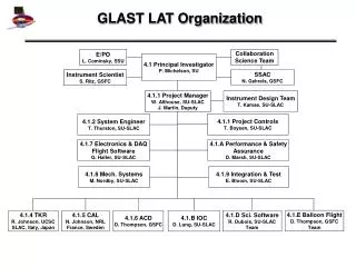
Stanford University GLAST LAT TMCM Production Readiness Review February 2004. Presentation Summary. Overview of the Production Flow Details of the Individual Steps Process Summary Equipment Specialized Fixtures Production Capacity Inspection Notes Lessons Learned Questions.

E N D
Stanford University GLAST LAT TMCM Production Readiness Review February 2004
Presentation Summary • Overview of the Production Flow • Details of the Individual Steps • Process Summary • Equipment • Specialized Fixtures • Production Capacity • Inspection Notes • Lessons Learned • Questions
Assembly Flow Overview • Documentation to be used on the production floor • SLAC Assembly drawings LAT-DS-00898 LAT-DS-00899 • Teledyne Assembly Procedure (7108742) • Equipment / Flow is designed to meet a production capacity of 25 units per week
Assembly Flow Discussion Step 5.1 Kit Inspection • CFM Material received. Spec 7700530 • Lot traceability retained from supplier data • Material is inspected for count and damage • Homogeneous lot status is maintained
Assembly Flow Discussion Step 5.2 Flex Preparation • Prepare flex for attachment to the PCB • End cutting tool created to trim ends • Capacity matches daily needs • Lessons learned • Initially cutting of the flex ends was carried out after attach. This created issues with lifting of the flex circuit.
Assembly Flow Discussion Step 5.3 Pre-Attach Preparation • Prior to epoxy addition, Kapton is laid down over areas on PCB where epoxy is not needed. • Flex is abraded lightly to increase epoxy adhesion • Capacity matches daily needs • Lessons learned • Masking to avoid epoxy overflow • Abrading flex helps adhesion
Assembly Flow Discussion Step 5.4 Epoxy Dispensing • Epoxy is dispensed over stencil to form an even bond line on the backside of the flex • Extra Long Stencil Printer and custom stencil created due to length of PCB • Issues. Voiding and bubbles in pre-frozen epoxy caused several issues with applying epoxy, required centrifuge • Lessons learned • Epoxy could not be pushed through a screen, needed a stencil • Epoxy has a better consistency/longer shelf life/fewer bubbles, if mixed at Point Of Use rather than bought frozen
Assembly Flow Discussion Step 5.5 Flex Attach to PCB • Flex is held in place while being wrapped around PCB radius edge • Specialized bending fixture holds all in place during cure. PCB is attached to a metal carrier plate to stop PCB flexing during almost all steps • 3 bend fixtures required to meet daily capacity • Inspection Notes / Criteria added to process spec to meet Italian needs • Issues. Voiding and bubbles in pre-frozen epoxy caused several issues with lifting and voiding between PCB and flex • Lessons learned • Cutting of PCB radius edge very critical to entire production
Assembly Flow Discussion Step 5.6 Cure • Standard oven cure 80ºC for 1.5 hours • Capacity matches daily needs
Assembly Flow Discussion Step 5.7 Flex Cutting • Excess flex material is trimmed away from PCB • Specialized fixture, two parallel tracks hold a cutting wheel in place as it cuts both Italian and Teledyne sides separately • Capacity matches daily needs • Lessons learned • Early on, use of any knife to cut did not produce a consistent cut line • Method of attaching right angle piece to PCB critical to cut consistency • PCB/ carrier must be cooled down to room temp prior to cutting. Otherwise cut will not be straight due to epoxy/flex movement
Assembly Flow Discussion Step 5.8 Post Cure Flex Inspection • Inspection of completed PCB/Flex to meet the needs of both Italian and Teledyne wire bond operation • Capacity matches daily needs • Lessons learned • All inspection stations need a holding plate to stop PCB length from rocking on a standard mount
Assembly Flow Discussion Step 5.9 SMT Component Attach • Apply solder paste and attach SMT components (Mydata), reflow (Vitronics), and clean (Forward Tech) • Specialized stencil created to apply solder paste. Has a lip to stop paste reaching flex circuit. Parts laid in opposite direction • Capacity matches daily needs • Lessons learned • Regular screen printing will not work • Dispensing of solder paste too slow to meet production capacity
Assembly Flow Discussion Step 5.10 Connector Attach • Omnetics connector manually screwed to PCB attach Process Details • Torque screw drivers pre set to 8-10 inch ounces • Capacity matches daily needs • Lessons learned • Original design of Omnetrics connector was weak allowing separation of the plastic encasing the pins from the metal body • Initial design had 2 sets of PCB countersunk holes, plus did not work well, revised PCB solved this
Assembly Flow Discussion Step 5.11 ASIC Attach • Epoxy applied and ASIC attached per Assembly drawing • Process Equipment (present Manual, volume production planned Automated) • Lessons learned • Assembly drawing needed clear instructions for alignment
Assembly Flow Discussion Step 5.12 Wire Bond • 3000 1 mil Al wire bonds added to connect ASIC to ASIC, ASIC to PCB & ASIC to flex. Clean prior with Tepla plasma. Pull test verification at start/intervals and NDPT during bonding on Dage 4000 • Capacity matches daily needs • Issue, due to PCB length only 1/2 can be bonded at a time (wire bond machine does not have enough table travel • Lessons learned • Original angled traces caused issues with pattern recognition. Redesigned to straight traces • Remove use of Wire Bond Protection enclosed fixture. Although works well protecting wires once inserted, the multiple insertion/removal steps can result in more damage to the wires.
Assembly Flow Discussion Step 5.13 Manufacturing Inspection • Parts inspected to meet SOW requirements prior to electrical test • Capacity matches daily needs
Assembly Flow Discussion Step 5.14 Pre-Encapsulation Electrical Testing • Each TMCM tested to SLAC document Process (LAT-DS-01971 ) by SLAC personnel • Grounding cover used • Learned lessons • Needed an additional screw to ground PCB to carrier plate to reduce noise at test • First series of testing had high percentage of ASIC’s failing, subsequent wafer testing has reduced this percentage although there still appears to an unknown reason why KGD fails • Greater information relating to “Pass” “Fail” added to data print outs along with information on the number of channels failing to assist production to understand status of TMCM coming from test
Assembly Flow Discussion Step 5.15 QC Inspection • Capacity matches daily needs • Inspection to IPC 610 and 7108742 • Lessons learned • Move inspection station to cell area
Assembly Flow Discussion Step 5.16 Encapsulation • Encapsulation dam applied over all wires • Encapsulation is in 2 parts, a dam and fill. Part sits on a heated stage to improve epoxy flow • Production Capacity • Issues, providing a thick enough fill to cover all the bond wires without excessive spreading of epoxy over entire TMCM • Lessons learned • Additional dam line added to top of flex to guarantee a keep away area for the Italian wire bonding, this also helped increase the thickness of the fill material over the • Due to slumping/settling of the epoxy, additional epoxy is manually applied at any exposed wires. Provided epoxy is added in the wet stage addition between two coats is OK
Assembly Flow Discussion Step 5.17 Conformal Coating • Conformal coating sprayed over TMCM • Areas masked off from spray. Grounding holes Italian wire bond area/traces down to bottom of encapsulation • Capacity matches daily needs • Coating thickness measured wet during process shift to meet IPC 610 criteria • Lessons learned • Addition to encapsulation not ideal, spray area lowered
Assembly Flow Discussion Step 5.18 Final Electrical Test • Final test by SLAC personnel. TMCM tested within plastic shipping box
Assembly Flow Discussion Step 5.19 QC Inspection • Final QC inspection to SOW
Assembly Flow Discussion Step 5.20 Customer Source Inspection • LAT QA appointed representative inspects TMCM
Assembly Flow Discussion Step 5.21 Shipping • TMCM placed in Plastic shipping box, vacuum packed in an ESD bag.
Assembly Flow Discussion Step 5.22 Die Rework • Remove bad die, localized heat on individual die • Hot Gas rework station • Issue with size of work area , need to add side supports for length • Leave some wires attached to ASIC die during die removal to stop die flipping off and damaging other wires
Assembly Flow Discussion Step 5.22 Wire Bond Rework • Standard 6400 machine Lessons learned • Pad size small to meet the 75% compound bond criteria, • Needed pad #’s adding to assembly drawing to assist in rework • Need to adjust reference points 1st bond to shift reference position to one side of pad
Cell Concept In line with Teledyne’s Philosophy, unique operations to this program will be co-located into a cell Action. Ongoing
Assembly Flow Discussion (1) Overall Lessons Learned • Traces can be damaged very easily, at early stages masking tape left on until wire bonding to protect from damage • Aspect ratio of TMCM requires careful handling to avoid damage • 3000 small 1 mil wires are a lot. All operators need to be aware of handling
Assembly Flow Discussion (2) Overall Lessons Learned • Various revisions of the PCB had different issues with component layouts. • ASIC pad sizes on initial PCB were incorrect, too small for IC size • Plating of PCB was not initially well defined • Marking of serial numbers was initially to be performed at Teledyne, changed to a screen print at PCB house. However first samples were confusing with characters badly defined • Original Cover layer on flex removed along with increased trace lengths to facilitate better alignment and cutting at Flex attach step
Fixture Status • Outstanding • Holding basket for PCB’s at SMT clean( Forward Tech). Ability to hold multiple carriers without each damaging other traces • Plasma cleaner support ( allow use of multiples of longer carrier tray) • Longer carrier tray (remove need for wire bond protection fixture). New carrier only used post wire bond to avoid any changes to flex attach fixturing • Larger WIP transport container • Length measurement fixture @ flex attach (SLAC) • Encapsulation Keep Away measurement fixture (SLAC)
Facility Infrastructure & Controls • Environmental Controls • Controlled Class 100,000 clean rooms. • Particle counts of areas, laminar flow hoods, and device storage areas measured on a regularly scheduled basis. • Statistical Process Control utilized for particle counts. • Temperature and humidity monitored and controlled. • Maintenance and shut-down procedures in place. • ESD Program • ESD Control Program in place. • Operators certified on a yearly basis. • ESD protective gowning. • Wrist straps and work stations verified daily plus constant monitors. • Grounded work stations with conductive table tops. • ESD protective packaging
GLAST Product Support Team Team MembersPosition • Rhonda Santiago Program Manager • Brian Caplen Project Engineer • Rick Careyette Director of Quality • Lupe Villegas Quality Engineer • Elvia Paez Manufacturing Manager • Sonia Andrade Production Team Lead • Ayub Patel Production/Material Control • Mike Faucher Operations Manager
GLAST Product Support Team Team MembersPosition/Role • Duc Tran Flex Attach/Conformal Coating Operator • Maribel Quinteros SMT Attach Operator • Julie Robles SMT Attach Operator • Maria Rodriguez Connector Attach Operator • Consuelo Perez Die Attach Operator • Virginia Torrez Die Attach Operator • Ana Castro Wire Bond Operator • Elvira Saldana Manufacturing Inspection • Annabel Sanchez Quality Inspection • Jose luis Saldana Encapsulation Operator • Peter Hansen Tooling Design Engineer • Steve Frangos Process Engineer (Wire bond) • Amanuel Risat Process Engineer (Epoxy Dispense) • Roger Briere Process Engineer ( Epoxy Dispense) • Jay Zakizadeh Process Engineer (SMT Pick & Place) • Tony Ostrowski Process Engineer ( SMT )