ECE 412: Microcomputer Laboratory
ECE 412: Microcomputer Laboratory. Lecture 9: The OPB Bus and IPIF Interface Cores. Outline. The OPB Bus Bus arbitration Using the IPIF core generators to build logic to interface your hardware to the PLB/OPB busses. Review Questions. What is time-multiplexed data transfer?

ECE 412: Microcomputer Laboratory
E N D
Presentation Transcript
ECE 412: Microcomputer Laboratory Lecture 9: The OPB Bus and IPIF Interface Cores Lecture 9
Outline • The OPB Bus • Bus arbitration • Using the IPIF core generators to build logic to interface your hardware to the PLB/OPB busses. Lecture 9
Review Questions • What is time-multiplexed data transfer? • Share a single set of wires for multiple pieces of data • Saves wires at expense of time • What are the two basic bus control protocols? What is the difference between them? • Strobe: Servant puts data on bus within time taccess • Handshake: Servant puts data on bus and asserts ack • How do the REQUEST, ADDRACK, RDACK, and WRDACK signals interact to control transfers over the PLB bus? • REQUEST starts a transaction, ADRACK acknowledges that the slave device has accepted the transaction, and RDDACK/WRDACK signal when data are received. Lecture 9
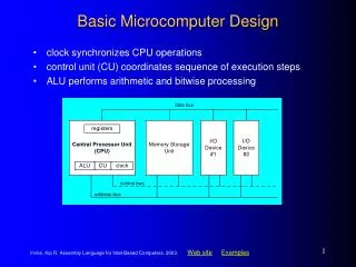
Micro- processor Cache Memory controller DMA controller Processor-local bus Peripheral Peripheral Peripheral Bridge Peripheral bus Multilevel Bus Architectures Revisit • Processor-local bus • High speed, wide, most frequent communication • Connects microprocessor, cache, memory controllers, etc. • Peripheral bus • Lower speed, narrower, less frequent communication • Typically industry standard bus (ISA, PCI) for portability • Don’t want one bus for all communication • Peripherals would need high-speed, processor-specific bus interface • excess gates, power consumption, and cost; less portable • Too many peripherals slow down bus Lecture 9
The OPB Bus • “On-Chip Peripheral Bus” • Standard developed by IBM for connecting logic cores to microprocessors/other cores • Not implemented in hardware by either the PowerPCs or the FPGA portion of the Virtex II Pro • Use Xilinx cores to build PLB-OPB “bridge” and interfaces • Use OPB because it’s enough of a standard that IP cores are designed to be compatible with it • Ex: the UART, SystemACE cores Lecture 9
OPB Bus • Two components: Arbiter and Interconnect • Interconnect implemented as OR of output bits from each master Lecture 9
OPB Bus • Specification supports up to 16 bus masters, arbitrary number of slaves • Number of slaves affects how many resources the OPB bus core uses • Xilinx recommends you use at most 16 slaves • 32-bit bus protocol • Signaling conventions similar to PLB • Xilinx core supports either combinational or registered control signals • Combinational allows responses in same cycle as requests • Registered generally allows higher clock rate on bus Lecture 9
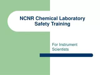
Micro-processor System bus 7 Inta 5 Priority arbiter Peripheral1 Peripheral2 Int 3 2 2 Ireq1 Iack1 6 Ireq2 Iack2 Arbitration: Priority Arbiter • Consider the situation where multiple peripherals request service from single resource (e.g., the OPB bus) simultaneously - which gets serviced first? • Priorityarbiter • Peripherals make requests to arbiter, arbiter makes requests to resource Lecture 9
Micro-processor System bus 7 Inta 5 Priority arbiter Peripheral1 Peripheral2 Int 3 2 2 Ireq1 Iack1 6 Ireq2 Iack2 Arbitration Using a Priority Arbiter 1. Microprocessor is executing its program. 2. Peripheral1 needs servicing so asserts Ireq1. Peripheral2 also needs servicing so asserts Ireq2. 3. Priority arbiter sees at least one Ireq input asserted, so asserts Int. 4. Microprocessor stops executing its program and stores its state. 5. Microprocessor asserts Inta. 6. Priority arbiter asserts Iack1 to acknowledge Peripheral1. 7. Peripheral1 puts its interrupt address vector on the system bus 8. Microprocessor jumps to the address of ISR read from data bus, ISR executes and returns (and completes handshake with arbiter). 9. Microprocessor resumes executing its program. Lecture 9
Arbitration: Priority Arbiter • Types of priority • Fixed priority • each peripheral has unique rank • highest rank chosen first with simultaneous requests • preferred when clear difference in rank between peripherals • Rotating priority (round-robin) • priority changed based on history of servicing • better distribution of servicing especially among peripherals with similar priority demands Lecture 9
OPB Bus Arbitration • Two modes • “Dynamic” gives priority to the LRU requester • “Fixed” defines a priority order for bus masters, gives bus to the highest-priority requester • Set of registers define priority order for fixed mode • Can be programmed before or during operation • Xilinx implementation of this is somewhat different than IBM spec in order to allow variable # of masters • User responsibility to make sure that every master has a slot in the table Lecture 9
OPB Bus Modes of Operation • Standard: Masters do individual requests for each transaction • Simple, but requires request-reply delay on each transaction • OPB bus does allow requests to overlap with transactions • Locked: Master can assert its lock signal to retain control of the bus for multiple transactions • Improves bandwidth, has potential for starvation if master doesn’t release bus • Parked: Master retains control of the bus as long as no other master requests it • Good bandwidth, no starvation, but masters need to watch for other requests Lecture 9
Interfacing Logic to the OPB/PLB Busses A number of challenges • PLB/OPB bus spec is somewhat complex • Each slave needs to detect whether the address of a request falls in its assigned range • PLB/OPB bus width may not match your logic • Many user cores require functions that aren’t built into the OPB/PLB bus spec • Bursts • DMA access • PowerPC handles interrupts and PLB with separate hardware Lecture 9
One Approach: Xilinx IPIF Cores • EDK includes a core generator that creates VHDL/Verilog for modules that act as the interface between user logic and the PLB or OPB busses • Core is parameterizable so that user can include just the functions that a given piece of logic needs • EDK provides a graphical interface to generate cores with most options • Refer to back-up slides Lecture 9
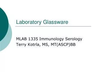
IPIF Functional Overview OPB or PLB Bus IPIF IP Interconnect (IPIC) User Logic Lecture 9
IPIF Functionality • Handles address range checking • Implements user-defined registers • “Byte Steering” lets devices connect to PLB/OPB busses that are wider than they are • Interrupt handling with collection/latching • Supports fixed length burst transfers • Read or Write FIFOs • DMA engine Lecture 9
IPIF Block Diagram Lecture 9
Things you can do with IPIF • Create a set of control registers for your logic so that you don’t have to deal with the PLB bus • We use this trick in MP2.1 • Instantiate a DMA engine to move data between a buffer (like a BlockRAM) and another device on the PLB bus (like, say, the SDRAM controller) • Using DMA engine simplifies your logic • Lets you ignore timing of the SDRAM • DMA controller can be configured to do scatter/gather to non-contiguous locations, making dealing with data structures much easier Lecture 9
More Things to do with the IPIF • Create input or output FIFOs • FIFOs are great for decoupling modules so that they don’t have to operate in lockstep • Also good for cases where your logic operates on blocks of data -- lets you think about transferring blocks instead of individual words • Issue reset operations to the processor • Doubt you’ll need that for this course, but useful in a number of real applications Lecture 9
Still more things to do with the IPIF • Manage interrupts • IPIF controller generates interrupts for DMA, FIFO overflow, etc. • Need to merge user interrupts with IPIF controller interrupts • IP cores may implement interrupts differently than PowerPC • Different timing, hold requirements, etc. • IFIP provides up to 32-bit bus of interrupt inputs • Some bits reserved for IFIP’s interrupts • If you need more interrupt signals than this, you need to build a second device or an interrupt hierarchy. Lecture 9
Interrupts in the IPIF • IPIF provides two sets of interrupt registers: Device and IP • IP registers handle interrupts from user logic • Device registers are the interrupt information presented to the processor (merged user + IPIF interrupts) • Device registers always 32-bit, IP registers vary depending on number of interrupts defined • Interrupt Status Register is a bit vector of which interrupts are asserted • IPISR has three modes (defined per bit) • Pass-through (no latching) • Sample and hold (samples on clock edge and holds until cleared) • Registered edge detect (detect 0->1 transitions and hold) • Can also invert interrupt signals Lecture 9
Interrupts in the IPIF (cont’) • DISR merges IP and IPIF interrupt signals, is always pass-through • Device Interrupt Enable Register lets you enable or disable individual interrupts • Can also globally disable all interrupts • IP Interrupt Enable Register masks interrupts at the IP logic side • Device Interrupt Pending Register is bitwise and of DISR and DIER • Device Interrupt ID register contains ID of interrupt currently being sent to processor • IPIF interrupt logic selects highest-priority interrupt out of the ones asserted at any time Lecture 9
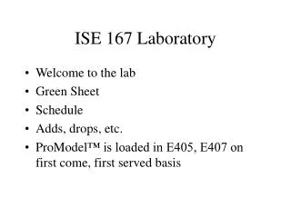
Using IPIF in MP2 • Core is provided to you in CP1 • V:\ece412\edk_user_repository\MyProcessorIPLib\pcores • Need to import existing core using “Create and Import Peripheral Wizard” • Need to create new core in CP2 • Design a median filter attached to OPB or PLB bus Lecture 9
Topology of Instantiated Modules for MP2 CP1 Mp2_checkpoint1 (mp2_checkpoint1.vhd) OPB_IPIF_I * User_logic (user_logic.vhd) Student_logic (student_logic.vhd: where your code will be written) My_logic (my_logic.vhd: simplified version of the DIO2 code we used in MP1 CP3) * Part of the EDK, not your project Lecture 9
BACKUP Slides for Creating the IPIF Core Lecture 9
Bus Interface Lecture 9
IPIF Services Lecture 9
Interrupt Service Lecture 9
User S/W Register Lecture 9
IPIC Lecture 9
Peripheral Simulation Support Lecture 9
Peripheral Implementation Support Lecture 9
You are done! Lecture 9
Next Time • Device drivers in Linux Lecture 9