Download
1 / 1
10 likes | 162 Vues
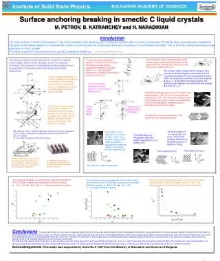
Institute of Solid State Physics. BULGARIAN ACADEMY OF SCIENCES. Surface anchoring breaking in smectic C liquid crystals M. PETROV, B. KATRANCHEV and H. NARADIKIAN. Introduction

E N D
Institute of Solid State Physics BULGARIAN ACADEMY OF SCIENCES Surface anchoring breaking in smectic C liquid crystalsM. PETROV, B. KATRANCHEV and H. NARADIKIAN Introduction The main problem in forming the smectic C (SC) liquid crystals (LCs) (growing upon cooling the nematic (N) LC) is the co-ordination of both the layer and molecular orientations. The goal of the present paper is to estimate the surface anchoring and the anchoring breaking by imposing of a controllable bulk twist. This is the first surface anchoring energy estimation in the SC phase. The phase transition temperatures of the used LC substance 8OBA are: The method of and ’ determination by the measurement of the azimuthal rotation of the polarizer P and analyser A of the microscope that result in optical extinction. One strong constraint on the layers at SC growth is to make a cone of angle, that of the SC tilt angle, around the imposed orientation. The existence of orientating boundary plates favours an orientation of the layers, which decreasing the conical degeneracy. The microtextural polarization analysis. The sample is illuminated with linearly polarized light, propagating normal to the glass plates. , ’ - the horizontal projections of n at the entrance and at the exit of the LCC. The sample rotation stage and the analyzer allow accurate azimuthal angular measurements. More convenient procedure is to fix the polarizer P and to rotate the sample by and then to turn the analyser A by ’. In the extinct (crossed) position, the absolute angle between the polarizer P and analyser A is thus 90’. The most typical peculiarity of the Sc revealed in the restriction of the director nto rotate (or reorient) around a cone with apex 2 inside layers; is the tilt angle between nand the layer normal N The scheme of the possible molecular positions in a completely twisting on 2 The SLM microtexture grown in LCC made by SiOx treated plates (82) at 0 in cross polarizes, magnification 125x. One notes also along the axis of the needles thin bright or dark lines (depending on the local polarization), indicating layer’s dislocations seen from the edge. The director ns near surface is under two constrains: it should be lie on the surface circular cone of angle /2 - , coaxial to the surface normal K and it should lie on the layer cone of angle (the smectic C tilt angle) The growing of tilted smectic C flat layers. The growing of vertical smectic C flat layers. The scheme of the microstructure of the layers S (l) and director positions. We used two kinds of liquid crystal cells (LCCs) according to substrates: (i) SiOx oblique evaporated on glass previously covered with ITO (SiOxITOglass); (ii) sinusoidal holographic diffraction grating. The SLM rotation on 4 (nons=45) for >c. The second possible disposition of the SLM long axis l is parallel to the no. The rotation of the SLM (l) in LCC made by SiOx (82) on a 2 with respect to the ‘easy’ no direction, implying the surface ns rotation on an angle 45 with respect to no. The SLM rotation by holographic diffraction grating orientation for 0 and nol45. amorphous S The scheme for >c. The scheme for 0. Scheme of the oblique evaporation of SiO on the ITO/glass plates. e, p, are the direction, plane and angle of evaporation and is the thickness of the oblique evaporated layer. Holographic gratings with a sinusoidal profile of amplitude A=50nm and surface undulation period =450nm. The scheme of the microstructure. S The azimuthal deviation =f() trends for bulk twist imposed on SiOx/ITO/glass surfaces and holographic diffraction grating. ▲ - SiO =60; ■ - SiO =82; ● – holograph diffraction grating. The azimuthal anchoring energy Ws=f() trend of azimuthal angle deviation on SiOx/ITO/glass surface (=82). The experimental data was fitted well with exponential decay. The azimuthal anchoring energy Ws=f() trends for bulk twist imposed on SiOx/ITO/glass surfaces and holographic diffraction grating. ▲ - SiO =60; ■ - SiO =82; ● – holograph diffraction grating. amorphous 1 S 2 amorphous ConclusionsThe surface anchoring in SC is an order of magnitude lower than that in the Ns at the same boundary conditions. We explain this effect with the complex character of the SC geometry, leading to the restriction of the director n (c) simultaneously to reorient around two cones: one with the substrate normal axis; and the other the layer normal axis. The holographic diffraction grating used reveals a rather smaller anchoring strength value than those of SiOx/ITO/glass which one can find in the small imposed twist (c) causing the SLM rotation (39 versus 70). Therefore, the SLM rotation could be easier drive by an imposed bulk twist in holographic grating. Furthermore, the achievement of very weak and controllable surface anchoring whatever is that of the holographic grating is one of the practical requirements. The sufficiently high value ns azimuthal deviation () with increasing provides limiting values of the anchoring strength parameters Ws0 and L which means an anchoring breaking (surface instability) with character of a I order surface transition. The microtexural polarization analysis shows that the l (meaning the layer plane direction S) rotates due to the imposed bulk twist from the angle range /4 with the ‘easy’ direction no to one including the angle 0 or /2 with this direction. Acknowledgements:This study was supported by Grant No.F-1307 from the Ministry of Education and Science of Bulgaria. crystalline Ta2O5