Input-output organization
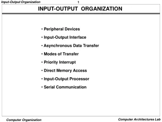
Input-output organization. External Devices I/O Modules Programmed I/O Interrupt Driven I/O Direct Memory Access I/O Channels and Processors. INTRODUCTION. The computer system’s I/O architecture is its interface to the outside world.

Input-output organization
E N D
Presentation Transcript
Input-output organization External Devices I/O Modules Programmed I/O Interrupt Driven I/O Direct Memory Access I/O Channels and Processors
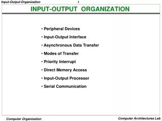
INTRODUCTION The computer system’s I/O architecture is its interface to the outside world. This architecture provides a systematic means of controlling interaction with the outside world and provides the operating system with the information it needs to manage I/O activity effectively. The are three principal I/O techniques: programmed I/O, in which I/O occurs under the direct and continuous control of the program requesting the I/O operation; interrupt-driven I/O, in which a program issues an I/O command and then continues to execute, until it is interrupted by the I/O hardware to signal the end of the I/O operation; and direct memory access (DMA), in which a specialized I/O processor takes over control of an I/O operation to move a large block of data.
The Evolution of I/O Function The evolutionary steps can be summarized as follows:- STEP 1: The CPU directly controls a peripheral device. This is seen in simple microprocessor controlled devices.
Step 2: A controller or I/O module is added. The CPU uses programmed I/O without interrupts. With this step the CPU becomes somewhat divorced from the specific details of external device interfaces.
Step 3: The same configuration as in step 2 is used, but now interrupts are employed. The CPU need not spend time waiting for an I/O operation to be performed, thus increasing efficiency.
Step 4: The I/O module is given direct access to memory via DMA. It can now move a block of data to or from memory without involving the CPU, except at the beginning and end of the transfer.
Step 5: The I/O module is enhanced to become a processor in its own right, with a specialized instruction set tailored for I/O. The CPU directs the I/O processor to execute an I/O program in memory. The I/O processor fetches and executes these instructions without CPU intervention. This allows the CPU to specify a sequence of I/O activities and to be interrupted only when the entire sequence has been performed.
Step 6: The I/O module has a local memory of its own and is, in fact, a computer in its own right. With this architecture, a large set of I/O devices can be controlled, with minimal CPU involvement. A common use for such an architecture has been to control communication with interactive terminals. The I/O processor takes care of most of the tasks involved in controlling the terminals.
The I/O channel represents an extension of the DMA concept. An I/O channel has the ability to execute I/O instructions, which gives it complete control over I/O operations. In a computer system with such devices, the CPU does not execute I/O instructions. Such instructions are stored in main memory to be executed by a special-purpose processor in the I/O channel itself. Thus, the CPU initiates an I/O transfer by instructing the I/O channel to execute a program in memory. The program will specify the device or devices, the area or areas of memory for storage, priority, and actions to be taken for certain error conditions. The I/O channel follows these instructions and controls the data transfer.
Types of I/O Channels • Selector Channel : A selector channel controls multiple high-speed devices and, at any one time, is dedicated to the transfer of data with one of those devices. Thus, the I/O channel selects one device and effects the data transfer. Each device, or a small set of devices, is handled by a controller, or I/O module, that is much like the I/O modules we have been discussing. Thus, the I/O channel serves in place of the CPU in controlling these I/O controllers.
Multiplexor Channel :A multiplexor channel can handle I/O with multiple devices at the same time. For low-speed devices, a byte multiplexor accepts or transmits characters as fast as possible to multiple devices. For example, the resultant character stream from three devices with different rates and individual streams A1A2A3A4 . . ., B1B2B3B4 . . ., and C1C2C3C4 . . . might be A1B1C1A2C2A3B2C3A4, and so on. For high-speed devices, a block multiplexor interleaves blocks of data from several devices.