Airports, Airspace, and Flight Information
Airports, Airspace, and Flight Information. Chapter 3 Section A. Airport Environment. Runway Markings. Visual Runway Marked with runway marker and centerline Non-Precision Instrument Runway Visual runway markings, threshold, and aiming point markings Precision Instrument Runways

Airports, Airspace, and Flight Information
E N D
Presentation Transcript
Airports, Airspace, and Flight Information Chapter 3 Section A
Runway Markings • Visual Runway • Marked with runway marker and centerline • Non-Precision Instrument Runway • Visual runway markings, threshold, and aiming point markings • Precision Instrument Runways • Served by nonvisual precision approach aids, such as ILS. • Uses Glide Slope to provide glide path information during the approach
Taxiway Markings • Links between airport parking areas and the runways. • Identified by continuous yellow centerline stripe • Occasionally, used to define the edge of the taxiway • Hold Lines: used to keep aircraft clear of runways and at controlled airports, serve as the point that separates the ground control from those of the tower.
Additional Markings • Displaced Threshold: marked by solid white line extending across the runway perpendicular to the centerline. Marks point of which all normal takeoffs and landing operations are permitted. • Blast pad/ Stopway areas: marked with yellow chevrons and may not be used for taxiing, takeoffs, and landings. Allows propeller or jet blasts to dissipate without creating a hazard for others. The stopway provides additional paved surface for you to decelerate and stop.
Con’t • Demarcation Bar: Separates the displaced threshold area from a blast pad, Stopway, or taxiway that precedes the runway. • Close Runways are marked with a large yellow “X” at each end
Airport Signs • Fig. 3-5 • Most airport signs are standardized for easy identification. • Six types of signs: • Mandatory • Location • Direction • Destination • Information • And Runway Distance Remaining
Runway Incursion Avoidance • Primarily caused by errors associated with clearances, communication, airport surface movement, and positional awareness. • 1. Study airport layout during preflight planning. • 2.Complete as many checklists items as possible before taxi or holding short • 3.Read back (in full) all clearances • 4.While taxiing, know precise location and concentrate on primary responsibilities.
Con’t • 5. If unsure of position, stop and ask for assistance • 6. When possible, while in run-up or waiting for clearance, position aircraft so you can see landing aircraft. • 7. Monitor appropriate radio frequencies • 8. After landing, stay on tower frequency until instructed to change • 9.Use exterior taxi/landing lights • 10. Report deteriorating or confusing airport markings, signs, and lighting • 11. Make sure you understand the required procedures if flying into an airport where land and hold short operations are in effect.
Approach Light System • Sequenced Flashing Lights (SFL) • Runway Alignment Indicator Lights (RAIL) • Consist of a series of brilliant blue-white bursts of flashing light. • Fig 3-9 • Runway End Identifier Lights (REIL) • Appear with green threshold lights to help you identify the threshold of a runway surrounded by a preponderance of other lighting.
LAHSOLand and Hold Short Operations • The PIC has the final authority to accept or decline any LAHSO clearance. • To prepare for a possible LAHSO clearance, become familiar with all available information for use of these procedures at the destination airport. • If there is any doubt you can land and stop within the ALD, you should decline a LAHSO clearance. In this instance, notify ATC as soon as possible • Have good understanding of airport markings
Visual Glide Slope Indicators • Two-bar system provides one visual glide path, normally set to 3° • Staying on the VASI glide path assures you of safe obstruction clearance within ±10° of the extended runway centerline and out to 4 nautical miles from the threshold.
Runway Lighting • Runway edge lights: outline the runway during periods of darkness or restricted visibility. Classified according to their brightness • HIRL- High intensity runway lights • MIRL- Medium intensity runway lights • LIRL- Low intensity runway lights • Threshold Lights: Mark ends of each runway • Displaced threshold lights: appear green during approach to a landing, do not land short of these lights.
Con’t • Touchdown Zone Lighting (TDZL): • Helps identify touchdown zone when visibility is reduced. • Runway Centerline Lights( RCLS): • Flush-mounted in the runway to help you maintain the centerline during takeoff and landing • Land and Hold Short Lights: • Row of five flush-mounted flashing white lights installed at the hold short point, perpendicular to the centerline of the runway on which they are installed.
Con’t • Taxiway lead-off Lights: • Generally are flush-mounted alternating green and yellow lights spaced at 50- foot intervals • Taxiway centerline lights- green • Taxiway edge lights- blue • Pilot-Controlled Lighting: • Designed to conserve energy and may be found at some airports which do not have full –time power
Airport Beacons and Obstruction Lights • The beacon is designed to help locate the airport at night and during conditions of reduced visibility. • During the day in controlled airspace Class B,C, D, and E may indicate ground visibility is less than 3 statute miles and/ or the ceiling is less than 1,000 feet. • Red flashing light beacons indicate obstructions that are hazardous to aircraft.
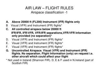
Controlled Airspace • Defined dimensions within which air traffic control service is provided to IFR flights and to VFR flights in accordance with airspace classification • Class A, B, C, D, and E Airspace • To fly in controlled airspace, within the contiguous United States, your aircraft must meet certain equipment requirements.
Class A, B, C, D, and E Airspace • Class A: extends from 18,000 feet MSL up to and including FL600. VFR flight not permitted. • Class B: established to separate all arriving and departing traffic; Surface up to 10,000 feet MSL. • Class C: must establish two-way communication with ATC as soon as practicable. Consist of two circular areas which extend outward from the primary airport and area and the 10 nautical mile radius shelf area. • Class D: ATC communication established with ATC before entering. Transponder not required. Ceiling is usually 2,500 feet above the surface of the airport converted to mean sea level, and rounded to the nearest 100-foot increment. • Class E: Begins at 14,500 and 18,000 feet MSL. One portion consists of airspace covering 48 contiguous states, District of Columbia, and Alaska. • Refer to Fig: 3-18
Special VFR • Require you to maintain a minimum ground visibility ( or flight visibility, if ground visibility is not reported) of one mile and remain clear of clouds.
Class G Airspace (Uncontrolled) • Maximum altitude for is 14,500 feet MSL, except where that altitude is below 1,500 feet AGL. • As shown in figures 3-14 and 3-20, the VFR minimums at or above 10,000 feet MSL ( and more than 1,200 feet AGL) are the same in Class G and E airspace. • Except for temporary control towers, ATC does not exercise control of air traffic in Class G airspace.
Aircraft Speed Limits • Normally, the maximum indicated airspeed permitted when at or below 2,500 feet AGL within 4 nautical miles of the primary airport of a Class C or Class D airspace is 200 knots.
Special Use Airspace • Prohibited Areas: flight is prohibited due to security or other reasons associated with National Welfare. • Restricted Areas: often contain visible hazards to aircraft such as artillery firing, aerial gunnery, or flight of guided missiles. • Warning Area: extending from 3 Nautical miles outward from the coast of the United States, that contains activities that may be hazardous to non-participating aircraft. • Alert Area: may contain high volume of pilot training or an unusual type of aerial activity, such as parachute jumping or glider towing. • Military Operations Areas (MOAs):designed to separate military activities from IFR traffic. • Controlled Firing Areas: activities are discontinued immediately when spotter aircraft, radar, or ground lookout personnel determine an aircraft might be approaching the area.
Other Airspace Areas • National Security Areas(NSAs): established at locations where there is a requirement for increased security and safety of ground facilities. • Local Airport Advisory Areas: extend 10 statute miles from airports where there is a flight service station located on the field and no operating control tower. • Temporary Flight Restrictions: imposed by the FAA to protect persons and property on the surface or in the air. • Terminal Radar Service Areas (TRSAs): do not fit into any of the U.S. airspace classes.
ADIZ • Air Defense Identification Zones: designed for aircraft to provide identification prior to entering U.S. domestic airspace from points outside . • Defense VFR (DFVR): File when flying VFR; contains information similar to local flight plans, but helps to identify your aircraft as you enter the country.
Aeronautical Information Manual • Contains fundamental information required for both VFR and IFR flight operations withini the National Airspace System • Revised 2x in one year
Airport/Facility Directory • Is a series of regional books ( also available on the FAA website) which includes a tabulation of all data on record with the FAA for public-use civil airports, associated terminal control facilities, air route traffic control centers, and radio navigation aids. • Fig. 3-23
Notices to Airman ( NOTAMs) • Contain time-critical, aeronautical information that could affect your decision to make a flight
International Flight Information Manual • Is an online FAA document that contains the requirements and instructions for flying outside the United States. • Intended for Pre-flight planning by nonscheduled operators.
Advisory Circulars • Provides current aviation information on a recurring basis, the Department of Transportation publishes and distributes advisory circulars.
Works Cited • Jeppesen. Guided Flight Discovery: Instrument Commercial. Englewood, CO, 2013.