Download
1 / 50
520 likes | 680 Vues
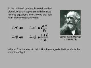
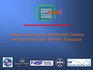
2. A New Generation Submillimetre Camera for the James Clerk Maxwell Telescope. 2. Presentation Outline. Scientific priorities and requirements Why do we need a SCUBA-2? Project performance Competitiveness and complementarity. Instrument design Detector and readout technology

E N D
2 A New Generation Submillimetre Camera for the James Clerk Maxwell Telescope
2 Presentation Outline • Scientific priorities and requirements • Why do we need a SCUBA-2? • Project performance • Competitiveness and complementarity • Instrument design • Detector and readout technology • Cryogenic system • Optical and system design • Status report
2 Science Priorities and Requirements
2 Why do we need SCUBA-2? • Utilise the large field-of-view of JCMT to open-up new fields of study • New technologies Larger format arrays • Increase scientific productivity of telescope • Maximise the returns with impending arrival of SMA link and heterodyne arrays • Keep the JCMT at the forefront of submm continuum astronomy
2 Scientific Aims What kinds of science does the JCMT community want to do? • Deep imaging reach the confusion limit in only an hour or two
The formation of galaxies, stars and planets Hubble Deep Field (N) : Hughes et al. 1998 Protoplanetary dust disks formation of planets and planetesimals Eagle Nebula (M16) : White et al. 1999 Large-scale extragalactic surveys formation and evolution of galaxies Protostars and pre-stellar cores the earliest stages of star formation Eridani : Greaves et al. 1998
2 Scientific Aims What kinds of science does the JCMT community want to do? • Deep imaging reach the confusion limit in only an hour or two • Large Scale mapping map several square degrees of sky in a few hours
Unbiased large-scale surveys of the Galaxy 450m SCUBA F-O-V SCUBA-2 F-O-V 850m SCUBA Survey of the Galactic Centre (Pierce-Price et al. 2000)
2 Scientific Aims What kinds of science does the JCMT community want to do? • Deep imaging reach the confusion limit in only an hour or two • Large Scale mapping map several square degrees of sky in a few hours • Dual-colour imaging/photometry investigate dust properties
2 Scientific Aims What kinds of science does the JCMT community want to do? • Deep imaging reach the confusion limit in only an hour or two • Large-scale mapping map several square degrees of sky in a few hours • Dual-colour operation investigate dust properties • Known-position point-source photometry define the spectral energy distribution
Photometric studies of point sources Defining the spectral energy distribution SCUBA IRAM-30m T=30K, =2 (Ivison et al. 1998) Radio galaxy 8C 1435+635
2 Main Scientific Drivers • Maximum mapping speed is the top priority goal is for at least 100 times that of SCUBA • Point-source sensitivity is nearly as important per-pixel sensitivity at least 50% better than SCUBA • Operation at two wavelengths simultaneously 450 and 850m are the preferred choices
2 Main Scientific Drivers (2) • Maximising the field-of-view is more valuable than extra wavelengths goal is for at least 8 8 arcminutes • No sky-chopping is preferable particularly for confusion-limited surveys • Image fidelity and map dynamic range “sharper” images-improved quality data Faster, deeper, better...
2 Baseline Instrument Design • Two arrays operating at 450 and 850m simultaneously • Each array instantaneously samples the sky • Field-of-view on the sky is 8 8 arcminutes • Sky-background limited performance • Pixels are DC-coupled
2 LMT-BOLOCAM 1.1mm CSO-BOLOCAM 1.4mm Future Bolometer Arrays in the Submillimetre Timeline: 1999 Timeline: 1999 2001 2003 2004 2007+ JCMT-SCUBA 350/450 & 750/850mm SOFIA-HAWC 200mm FIRST- SPIRE 250, 350, 450mm SIRTF-MIPS 160mm CSO-SHARC-II 350/450 JCMT-SCUBA2 450/850mm SCUBA+ (JCMT) Bolocam (CSO) MIPS (SIRTF) HAWC (SOFIA) SHARC-II (CSO) Bolocam (LMT) SCUBA-2 (JCMT) SPIRE (FIRST) 91/37 pixels 300/65 mJy 40 160 384 600 151 3 144 40 384 560 32/72/128 ~40 22500/6500 100/20
Field-of-view of current and future arrays Current Future Wavelength : 200 300 400 500 700 900 1200 2000 (microns)
Competitiveness of SCUBA-2 Increasing effectiveness
Complementarity of SCUBA-2 (Ivison et al. 1998) Radio galaxy 8C 1435+635
2 Comparison with other instruments
2 Key science with SCUBA-2... • Deep, large-scale extragalactic surveys A couple of examples: • Large-scale, high-resolution galactic surveys
Confusion-limited surveys A P3 N-bodysimulation of a confusion-limited 1 deg2 area of sky with the JCMT at 850m Unbiased surveys of different sizes and depths for studying the formation of massive galaxies Hughes and Gaztanaga, 2000
Large-scale surveys and galaxy clustering • Shows positions of luminous dusty starburst galaxies tracing the large-scale structure at early epochs • Large sample sizes (~5000) can test theories of structure formation • SCUBA-2 can carry out large, sensitive and unbiased surveys in modest amounts of time ~ 1 arcmin CDM simulation at z ~ 3 (Governato et al. Nature 1999)
Galactic Centre SCUBA Galactic Centre Survey M8 ~ 15 shifts (or 120 hrs) of telescope time M16 SCUBA-2 Galactic PLANE Survey?
2 Instrument Design
Bolometer Principles Submm radiation Load resistor RL Spider-web absorber, Temperature Tbol Heat capacity C Thermal conductance G JFETs Vout VBias NTD thermometer Rbol Load resistor RL Heat sink Temperature To
2 I 0.06 SQUID Amplifier Rbias 0.04 Resistance (Ohms) Vbias 0.02 R(T) TES 0 95.8 96 96.2 Temperature (mK) Voltage-Biased Superconducting Transition-Edge Sensors • Voltage-biased on normal - superconducting transition • Resistance is a very steep dependence on temperature in transition region • Film held at constant voltage bias - change in resistance results in a change in current through the film
2 I SQUID V P joule V P res R TES Thermal conductance Heat Reservoir Negative Electrothermal Feedback • Bias power or joule heating depends on resistance of the superconducting film Thermal/electrical Circuit • As the film cools, its resistance drops and the joule heating increases • The joule heating provides negative feedback raising the film temperature • A stable equilibrium occurs when the joule heating matches the heat loss 2 V2 Pres R Temperature Self-Regulation
2 Normal metal Superconductor Substrate Superconductor / Normal Metal BilayerTransition-Edge Sensor Superconductors in use: Aluminum Tc ~ 1.1 K Molybdenum Tc ~ 0.92 K Titanium Tc ~ 0.4 k Iridium Tc ~ 0.14 K • A bilayer of a thin superconducting film and a thin normal metal acts as a single superconductor with a • tunable - the “proximity effect” • Sharp • Reproducible ~2 mK • Tunable
TES Device Processing High resolution micromachined Mo/Cu x-ray detector Phonon noise limited Mo/Cu “pop-up” IR detector Mo/Cu process has been used to make high performance detectors for a variety of applications
Metal absorber 5mm Si grid Reflector l/4 cavity MICROMACHINED ARRAY FOR SCUBA-2 Mechanical/thermal/electrical link TES Absorbing metal film l/4 cavity Silicon substrate Reflector Silicon grid 100mK 50 mm • Silicon grids (or sheet) with absorber • TES (R ~ mW) • Interconnect and multiplexer chip 400 mm TES 100mK Absorbing grid Reflector/SQUID Indium bumps
Metalised silicon grid absorber with l/4 reflector Implanted thermometer CEA-SACLAY/LETI16 16 PROTOTYPE ARRAY
2 Practical issues for TES devices • Need for high-speed readout-Wiring and warm electronics non-trivial for for large format arrays • Magnetic shielding • 1/f noise • Robustness- survival of multiple thermal/vacuum cycles • Coping with uncertain background
Mo-Cu PUD with thick normal bars -16 10 In*V (Watt/sqrt(Hz) -17 10 -1 0 1 10 10 10 Frequency (Hz) Recent low-frequency test results 1/f noise dominated by amplifiers. Near the bottom of the transition, the responsivity is highest, and the 1/f knee is ~100 mHz. Biased near top of transition Biased near bottom of transition
2 Feedback Flux I SQUID Output Voltage SQUID Amplifier Input Coil Rbias SQUID Bias Current LIN Vbias X X LFB R(T) TES SQUID readouts • TES is voltage-biased and of low impedance: SQUIDs are ideal for measuring the I in these detectors • TES is wired in series with a SQUID ammeter • Each SQUID has a current bias input and voltage output • There is also a separate feedback coil to linearise the response of the SQUID • Therefore six wires per SQUID are required 180,000 wires for SCUBA-2!
2 Column Flux Bias Column Output Column 2 Column 1 Addr. 1 RADD RADD LIN LIN X X X X LIN LFB X X LFB LFB Row 1 Addr. 2 RADD RADD LIN LFB LIN X X X X LIN X X X LFB X LFB Row 2 Addr. 3 RADD RADD Addr. N RADD RADD LIN LIN X X X X LFB LFB Row N LIN LFB Addr. N+1 RADD RADD SQUID Multiplexers • NIST have developed a method to multiplex the SQUID readouts for large format arrays • Output of N SQUIDs connected in series - each SQUID biased one at a time (time division) • Scheme means that only 2 bias and output lines are needed per column of SQUIDs • Single column multiplexers can be placed in parallel • SCUBA-2 450m array can be realised with only 801 wires...
2 100 mK 0.8 K TES bolometers on micro-machined pixels Bump-bonds SQUID arrays Wire bonds Wire bonds Ribbon cables Multiplexer SQUID and interconnect/back plane chip Wire bonds 100 mK Ribbon cables Buffer amplifiers and SQUID multiplexer Electronics functional diagram 300 K
2 Illuminationpattern D Filled arrays as an alternative to feedhorns • Array of square bolometers as bare pixels (just as in a CCD camera) • Pixel size = 0.5 Ffor full spatial sampling • Pixel field-of-view is wide (~ steradians) • Illumination to the telescope must be defined by a cold stop Cold enclosure • Near top-hat illumination of the telescope
2 Filled (bare) arrays • AdvantagesInstantaneous full sampling of the image Higher efficiency (speed) for mapping Slightly narrower beam on the sky • Disadvantages Lower speed for known point source observation Greater vulnerability to stray light Greater vulnerability to RF interference ~ 12 times more detectors for a given field of view ~ 4 times lower background per pixel NEPPH lower by a factor of ~ 2
Array boundary Vignetted area ~11arcmin ~8 arcmin 95 arcmin2 64 arcmin2 (A) Maximum F-O-V (B) Minimum F-O-V SCUBA-2 Field-of-view How many pixels do we need? 450m: 38,000 25,600 850m: 9,500 6,400
2 Operating temperature Three factors push the operation of SCUBA 2 array to the 100 mK region:- • Margin on power handling • Engineering margin on background limited NEPs to account for non-ideal performance amongst large number of pixels • Multiplexer power dissipation - NIS junctions run at 100mK
2 0.06 Total power Pmax 0.04 Resistance (Ohms) Bias power Bias power 0.02 Sky power Sky power 0 95.8 96 96.2 Temperature (mK) Good sky Poor sky Power Handling • The sharp n-s transition means that there is a fixed power level that a TES can handle • This is the power required to warm the device from the base to transition temperature • It is the sum of the bias and sky power • In a practical device it is important to have some headroom in the power handling to allow for a miss-estimation of background levels • To achieve more power headroom the base temperature has to be decreased
2 What it might look like...
2 Current Status
2 SCUBA-2 Project Four phases to the project: • Pre-Select Phase • Technology development and verification • Science instrument construction and lab testing • Delivery and telescope commissioning
SCUBA-2 Proposal Timescales JCMT Community Questionaire Technical discussions NIST discussions Jun 99 SCUBA-2 Proposal Oct 99 JCMT Board Review CoDR Nov 99 Pre-Select Phase PPARC Astronomy Committee Technical discussions NIST contract work Jan 00 Pixel Arch Down Select May 00 JCMT Board Review May 00
Detector development and verification Timescales Science Instrument Systems analysis Sub-system design Prototype array and electronics Order long lead items Jul 00 Technology Verification Jul 02 Key sub-systems ready First lab tests Nov 02 Science arrays and electronics Jul 04 Telescope I infrastructure Integrate and lab test Delivery and commissioning Delivery to Hawaii Jul 05 Telescope commissioning Science Operations Dec 05
2 “COST PER PIXEL” UKT14 1 1 $800,000 SCUBA 131 ~7000 $70,000 SCUBA-2 30,000 >106 $250