Introduction to CMOS Technology
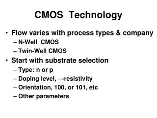
Introduction to CMOS Technology. C. Fenouillet-Beranger SOI Devices Engineer, CEA/LETI & STMicroelectronics, Crolles. Outline. MOSFET Basics Ideal MOSFET physics Main parameters : threshold, leakage and speed What MOSFET for what application ?

Introduction to CMOS Technology
E N D
Presentation Transcript
Introduction to CMOS Technology C. Fenouillet-Beranger SOI Devices Engineer, CEA/LETI & STMicroelectronics, Crolles
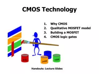
Outline • MOSFET Basics • Ideal MOSFET physics • Main parameters : threshold, leakage and speed • What MOSFET for what application ? • Scaling theory and good design rules of CMOS Devices • The Real World • Threshold voltage control limitations • Gate oxide leakage and capacitance scaling • Technological Solution ? • Gate alternative : High-K and Metal Gate • Channel engineering : Strained-Si • Alternative devices and substrates • Basic logic functions
Different scales inside a chip Gate 2x2 cm² 10x10 mm² Source Drain NiSi NiSi Silicon channel 4x4 µm² 500x500 nm²
Making a Switch with Metal, Oxide and Silicon E Energy Barrier C = S D Carrier reservoir Source Drain x Vg Energy Barrier 0 Metal Carrier reservoir Oxide Source n+ n+ Si (p) Drain x Vd
VG=0V VG>0V What is an ideal MOS Transistor ? G G VS=0V VD>0V VS=0V + + + + + + VD>0V D D S S - - - - - - - IDS Canal vide : courant nul Canal rempli : courant non nul A TMOS bloqué B TMOS passant A MOS capacitor is modulating the transport between two carrier reservoir ON-STATE OFF-STATE MOS capacitance : Field Effect MOSFET
n-type & p-type MOSFETs Vg<0 Vd>0 Vd<0 0 Metal Oxide p+ p+ Si (n) Vg>0 0 Metal Oxide n+ n+ Si (p) nMOSFET Electron conduction pMOSFET Hole conduction
MOSFET morphology Gate (Poly-Si) Métal Oxyde Semi- conducteur Si Source Drain
Basic Physics of MOSFET ON state Current OFF state Current OFF State Current (Thermal) Threshold (Vth) Log(Idrain) MOSFET switch Ideal switch • 3 main parameters • Threshold Voltage • Ion (=speed) • Ioff (=stand-by power) Vgate
MOSFET Physics L nMOSFET VG=0 L VG=VD gate grille channel L VD VS L VD source drain VS Tox - - - - - canal source drain - - - Tox N N P - - - - - - + + + + N N P + + + WD/C + + WS/C P WD/C WS/C P - - - - - - - - - N - - - - - VB - BC d - - - - - - N N N VD BC VB « Off State» - - -
Threshold Voltage (Vth) L gate Channel Doping channel source drain WD/C WS/C P - - - - - - - - - Oxide Thickness N Gate Material BC N VD - - -
On State Current (Ion) Vg-Vth Vg-Vth-VDS Gate Lgate Source Drain L
Off – State Current (Ioff) VG1<Vth VG1<VG2<Vth Ithermique Idiffusion Ithermique Idiffusion VD>0 VD>0 Log Idrain - - - - - - - - - - - - + dec Ioff 1/S Vth Vgate Modulation of barrier heigth by Capacitive coupling S should be as small as possible
The Static Leakage Components i) Gate leakage (oxide thickness dependance) Ioff = IS + IG + IB ii) Channel Leakage (Vth and S dependant) iii) Junction leakage (doping dependance)
Different Applications : Some typical numbers Hifi – TV Computers Mobile Phones Low Vth Power Dissipation High Vth Operation Speed
CMOS Scaling CMOS032 CMOS045 CMOS065 CMOS090 CMOS120
Scaling Theory: Moore’s law • Gordon Moore, a co-founder of Intel said in 1965: • “Component count per unit area doubles every two years” • Last 40 years : technological advances achieved mainly by reducing • transistors size • - However current trend of miniaturization causes undesired effects degrading the electrical parameters and transistor performance • In reality: • µ decreases • Tox levels-off • Off current increases as transistor size is reduced
Ideal MOSFET Basics summary • Threshold Voltage : • Determines the gate voltage transition Vth between Off-state and On-state regimes • Vth depends (at the 1st order) on the channel doping and gate electrode material • On-State : • MOS gate capacitance lowers channel barrier • electrons(holes) flow from Source to Drain Ion current • Carrier transit time is Cgate*Vgate / Ion the higher Ion the faster the device • Off-State : • MOS gate capacitance potential = 0 • electrons(holes) flow from Source to Drain due to Thermionic current Ioff current • Static Power dissipation is Pstat = VDS * Ioff
Part 2. The Real World
Vth Control : Short Channel Effects Zone de charge d’espace ZCE Log Idrain SCE DIBL SCE DIBL BC VDS SCE=Short Channel Effect Vth Vth2 Vth1 DIBL=Drain Induced Barrier Lowering Vgate L
MOSFET Typical Lenghts and Ratios Lgate,phys Tox gate source drain Tdep Xj Lel Good design rules of MOSFET architecture : T T V X 1 ox 1 1 1 j dep th » » » » ; ; L 3040 L 3 L V 3 5 el el el dd
Scalingrules (MASTAR Model) VTH(short Mosfet)=VTH(long)-SCE-DIBL æ ö 2 X T T e ç ÷ j dep ox Si = + 0.8 SCE 1 V ç ÷ bi e 2 L L ç ÷ L ox el el è ø el æ ö 2 X T e ç ÷ T j dep ox Si = + 0.8 DIBL 1 V ç ÷ ds e 2 L L ç ÷ L ox el el è ø el 1 Wel = m I C (V V -Vth) dsat eff ox g dsat 2 Lel T. Skotnicki et al. IEEE EDL, March’88 & IEDM’1994
Why is it so difficult to get a « Good Scaling » ? Lgate,phys gate source drain Tdep Xj Lel Oxide Scaling Junction Scaling Doping increase Subthreshold control
Tox/Lel ratio : Gate Oxide Scaling Lgate,phys Poly-Si gate source drain Tdep Xj Lel zz zz
The Gate-Poly Silicon Depletion 20 20 NMOS ( NMOS ( Npoly Npoly =1e20cm =1e20cm - - 3) 3) , A , A 18 18 Tp Tp Tp (EOT) (EOT) (EOT) Vdd scaled 16 16 @ @ @ with Tox 14 14 1.8V 1.8V 1.8V polydepletion polydepletion 1.3V 1.3V 1.3V 12 12 1.0V 1.0V 1.0V 10 10 0.7V 0.7V 0.7V 0.5V 0.5V 0.5V 8 8 0.35V 0.35V 0.35V 6 6 0.25V 0.25V 0.25V EOT of EOT of 4 4 2 2 0 0 0 0 10 10 20 20 30 30 40 40 CMOS relevant CMOS relevant Tox Tox , A , A N+ P+ Tdeppoly = 0.4nm 0.6nm Ref.: E. Josse et al., IEDM’99
Quantization Effects in Inversion Layer C-Y. Hu et al., IEEE EDL, June 1996 ~150mV
Impact on Good Design Rule Reality Good design Rule Tox,eff = Tox + 8A
The problem of Gate Leakage Poly-Si Ec Ef Ev Ef Ec Ev Substrate Si P Gate N+ Si SiO2 Wpd 2 2A reduction in Tox ~ 1 dec increase in gate leakage
Impact of Gate Leakage on Circuits 0 1 1 0 0 0 Igoff Ioffcanal 0 0 If Tox , Ig , Power IgOn In Static Mode, two gate leakages: IgOff & IgOn : increase of Ioff
Vth/Vdd Ratio Log(I ) DS I off V V gs th If Vdd drops, just decrease the Vth too keep a good Ion. But … S degrades at smaller L !
What Did We Learn ? Junc. Leak. Ioff (power) increase Rs increase Ion (speed) reduction Gate leakage Higher Ioff Darkspace Limited Scaling Ion reduction Ion reduction Polydepletion Controlling Vth (Ioff) Increasing Doping Scaling Jonctions Scaling Tox ReducingVdd (power)
Whatcanwe do to retrieve a HealthyScaling ? Gate Source Drain NiSi NiSi Silicon channel Oxide Scaling Junction Scaling Low RSD for lower Xj Better Contact Resistance Less Gate Lekage No Poly Depletion Subthreshold control Vs Overdrive Doping increase Better Ion at the same overdrive Better Subthreshold Slope DIBL-Free Architecture
Ion Enhancement by materials Transistor Architecture Material Properties Velocity saturation regime Velocity Carrier velocity under electric field E in the linear regime: v = µ E µ Ecritical Efield
Mobility In Silicon 2 E = c v * m 2. High t (less possible collision) • Small m* : ligth electrons or holes t = µ q * m E Shockwave from lattice vibration, or impurities, or gate oxide rugosity every t seconds carrier, mass m* Effective mass of carrier Linked to valence/conduction bands
Who are the guys responsible for Ion ? (z) 001 (y) 010 6 equivalent types of electrons are involved in conduction regime of nMOS (x)100 ml 2 types of holes are involved in conduction regime of pMOS : heavy and light mt Silicon Band Structure
What happens in Strained-Si ? Splitting less intervalley phonon scattering Splitting Sub-band Carrier Redistribution Band structure deformation
Redistribution in subbands and scattering reduction Unstrained Si Strained-Si >80 % in HH < 1 % in HH N Fermi-Dirac E
Is Stress the Only Way to Enhance Mobility ? • Carrier effective mass can depend on cristal direction ! • For Electron iso-energy are ellipsoidal average dependance does not depend on Si direction for standard (100) substrate (not true in other direction) • For Hole : extremely high anisotopy of mass !! Heavy Mass Holes with the same energy Cristal Direction (3D) Light Mass
Choosing the right Si-orientation for Holes Standard (100) wafer 45° Rotation Light Mass along transport Rotated <100> channel Standard (100) wafer Heavy Mass along transport Standard <110> channel
Optimum Cristal Orientations • Inversion layer mobility depends on the surface orientations and current flow directions • For holes, mobility is 2.5x higher on (110) surface compared to standard wafer with (100) orientation • For electrons, mobility is highest on (100) substrates pMOS nMOS From M.Yang et al., IEDM 2004
Hybrid integration • To fully take advantage of the carrier mobility dependence on surface orientation, fabrication of CMOS on hybrid substrates has been demonstrated • The hybrid substrate is obtained using a layer transfer technique in which the bonded wafer and the handle wafer have different crystal orientation. An additional photo step is used to etch through the SOI and BOX and expose the surface of the handle wafer to perform SEG • Issues : limited scalability of bulk devices and increased process complexity [M. Yang et al., IEDM 2003]
MobilityEnhancement Techniques SixGe1-x Based Cristal Orientation Liners STI Bulk SSOI CESL SMT In-plane Out of plane SACVD SiGe Tensile Bi-axial Natural mobility boost Tensile Tensile bi-axial stress Tensile nMOS nMOS nMOS+pMOS pMOS Compressive nMOS+pMOS pMOS Si Mod.Orientation Si Channel box Cristal Orientation Rotated substrate BULK SSOI Process-based Induced Stess Substrate-based SiGe SEG SiGe SD Compressive pMOS
Strain and mobility Uniaxial compressive (along Lg) Uniaxial tensile (along Lg) Biaxial tensile [F. Payet, L2MP PhD, 2006]
Uniaxial Stress By Stressed-Liner Strained MOSFET (Lg=30nm) by CESL CESL Tensile 2D mecanical Simulations Impact on nMOSFETs performances Tension (F.Bœuf et al., IEDM 2004 , SSDM 2004)
Hole Mobility enhancement using Rotated Substrates 45° <100> <110> Current Flow
Uniaxial Stress using SiGe S/D <110> unstrained T.Korman +15% Courtesy, F.Payet