CMOS Technology
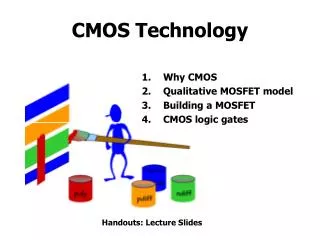
CMOS Technology. Why CMOS Qualitative MOSFET model Building a MOSFET CMOS logic gates. Handouts: Lecture Slides. Building Bits from Atoms. We Need Three Things: Represent and communicate bits Transform bits (Invert, AND, OR,…) Remember bits (storage).

CMOS Technology
E N D
Presentation Transcript
CMOS Technology • Why CMOS • Qualitative MOSFET model • Building a MOSFET • CMOS logic gates Handouts: Lecture Slides
Building Bits from Atoms We Need Three Things: • Represent and communicate bits • Transform bits (Invert, AND, OR,…) • Remember bits (storage) …subject to the fundamentals of physics: Uncertainty, Noise, c, Thermodynamics,…
Wish List • Small, simple, repeatable and stable non-linear devices with gainusing readily-available materials • Can mass produce very large quantities of devices and wires • Consistently improves performance and density (scales) with ongoing R&D investment
Wishes Fulfilled • Small, simple, repeatable and stable non-linear devices with gain using readily-available materials • Silicon + Aluminum/Copper + … • Can mass produce very large quantities of devices and wires • Literally print billions at a time • Consistently improves performance and density (scales) with ongoing R&D investment • Moore’s Law: 2x density every 1.5 to 2 years • ≈ $1T in cumulative investment
MOSFETS: Gain & non-linearity MOSFETs (metal-oxide-semiconductor field-effect transistors) are four-terminal voltage-controlled switches. Current flows between the diffusion terminals if the voltage on the gate terminal is large enough to create a conducting “channel”, otherwise the mosfet is off and the diffusion terminals are not connected. Why are MOS devices King?
FETs as switches The four terminals of a Field Effect Transistor (gate, source, drain and bulk) connect to conducting surfaces that generate a complicated set of electric fields in the channel region which depend on the relative voltages of each terminal. CONDUCTION: If a channel exists, a horizontal field will cause a drift current from the drain to the source. INVERSION: A sufficiently strong vertical field will attract enough electrons to the surface to create a conducting n-type channel between the source and drain.
“Linear” operating region Larger VDS increases drift current but also reduces vertical field component which in turn makes channel less deep. At some point, electrons are traveling as fast as possible through the channel (“velocity saturation”) and the current stops growing linearly.
Saturated operating region This looks just like a fet with a channel length of L’ < L. Shorter L’ implies greater IDS. As VDS increases, δL gets larger. When VDS = VGS-VTH the vertical field component is reduced and the channel is pinched-off. Electrons just keep traveling across depletion region…
NFET Summary Operating regions: linear: saturation:
FETs come in two flavors By embedding p-type source and drain in a n-type substrate, we can fabricate a complement to the N-FET: The use of both NFETs and PFETs – complimentary transistor types – is a key to CMOS (complementary MOS) logic families.
PFET Summary Operating regions: linear: saturation:
CMOS Inverter VTC When both fets are saturated, small changes in Vin produce large changes in Vout
Think Switches pullup: make this connection when VIN near 0 so that VOUT = VDD pulldown: make this connection when VIN near VDD so that VOUT = 0
Let’s build a MOSFET • Start with a 500μ slice of a silicon ingot that has been doped with an acceptor (typically boron) to increase the concentration of holes to 1014/cm3 - 1018/cm3. At room temperature, all the dopants in this p-type material are ionized, turning the silicon into a semiconductor. • We’ll build many copies of the same circuit onto a single wafer. Only a certain percentage of the chips will work; those that work will run at different speeds. The yield decreases as the size of the chips increases and the feature size decreases. • Wafers are processed by automated fabrication lines. To minimize the chance of contaminants ruining a process step, great care is taken to maintain a meticulously clean environment. So put on your bunny suits and let’s begin…
Creating patterns on the wafer • A “thick” (0.4u) layer of SiO2 is formed by oxidizing the surface of the wafer with wet oxygen (we rust it!). The SiO2 will serve as insulation between the conductive substrate and subsequent conductive layers we’ll build on top of the oxide. • Now we’ll form a pattern in the SiO2 using a mask & etch process. First the wafer is coated with a layer of photoresist. Photoresist becomes soluble when exposed to ultraviolet light… • Using a mask to protect parts of the wafer, we’ll expose those portions of the wafer where we want to remove the photoresist. We’ll use different masks when creating each of the different structures on the wafer.
The etching process • The exposed photoresist is removed with a solvent. The unexposed photoresist remains, masking portions of the underlying SiO2 layer. • A chemical etch is then used to remove the revealed silicon dioxide. • Finally, the remaining photoresist is removed with a different solvent and we’re left with pattern of insulating SiO2 on top of exposed p-type substrate.
Gate oxide & polysilicon • Now a “thin” (20 A) layer of SiO2, called gate oxide, is grown on the surface. The gate oxide needs to be of high quality: uniform thickness, no defects! The thinner the oxide, the more oomph the FET will have (we’ll see why soon) but the harder it is to make it defect-free. Coming soon to a fab near you: 12 A gate oxide... • On top of the thin oxide a 0.7u thick layer of polycrystalline silicon, called polysiliconor poly for short, is deposited by CVD. The poly layer is patterned and plasma etched (thin ox not covered by poly is etched away too!) exposing the surface where the source and drain junctions will be formed. Poly has a high sheet resistance of 20 Ω/sq which can be reduced by adding a layer of a silicided refractory metal such titanium (TiSi2), tantalum (TaSi2) or molybdenum (MoSi2) => 1, 3 or 5 Ω/sq.
Source/drain diffusions Donor implants are used to create self-aligned MOSFET source/drain diffusions and substrate contacts. Usually As is preferred to obtain shallow N-type diffusions and minimal lateral diffusion. High doses are needed to make low resistance (25 Ω/sq) diffusion wires. Afterwards a short thermal annealing step is performed to repair surface damage caused by the implantation. This completes the construction of the MOSFET itself. Now we’ll add the metal wiring layers…
Wires: metal interconnect After a layer of SiO2 insulation has been deposited, aluminum or copper is deposited, patterned, then etched to form low-resistance (.07 Ω/sq) interconnect. With planarization of the SiO2 (a mechanical polishing step that creates a flat surface), multiple levels of metal interconnect are possible -- 3 to 6 layers are common in today’s processes.
Standard Cell Layout for Inverter Physical design of a CMOS gate is represented by a mask layout showing where material on each layer (ndiff, pdiff, poly, m1, m2, …) should be placed on the silicon wafer. Each manufacturing process has a set of design rules that determine minimum widths, spacings, overlaps, etc.
Beyond Inverters:Complementary pullups and pulldowns We want complementarypullup and pulldown logic, i.e., the pulldown should be “on” when the pullup is “off” and vice versa. Since there’s plenty of capacitance on the output node, when the output becomes disconnected it “remembers” its previous voltage -- at least for a while. The “memory” is the load capacitor’s charge. Leakage currents will cause eventual decay of the charge (that’s why DRAMs need to be refreshed!).
General CMOS gate recipe Step 1. Figure out pulldown network that does what you want, e.g., F = A*(B+C) (What combination of inputs generates a low output) Step 2. Walk the hierarchy replacing nfets with pfets, series subnets with parallel subnets, and parallel subnets with series subnets Step 3. Combine pfet pullup network from Step 2 with nfet pulldown network from Step 1 to form fully- complementary CMOS gate.
Emerging Big Issue: Power Energy dissipated = C VDD2per gate Power consumed = f n C VDD2per chip Where f = frequency of charge/discharge n = number of gates /chip
Unfortunately… Modern chip (UltraSparc III, Power4, Itanium 2) dissipates from 80W to 150W with a Vdd ≈ 1.2V (Power supply current chip is ≈ 100 Amps) Ampacity is similar to a big double oven! Cooling challenge is like making the filament of a 100W incandescent lamp cool to the touch! Worse yet… Little room left to reduce Vdd nC and f continue to grow
Emerging Big Issue: Wires Today (i.e., 100nm): τRC ≈ 50ps/mm Implies 2ns to traverse a 20mm x 20mm chip This is a long time in a 2GHz processor
Summary • MOSFET features • PN junctions provide electrical isolation • Switch-like behavior controlled by VGS • Shrinking geometries improves performance • CMOS features • CMOS logic is “naturally” inverting: “1” inputs lead to “0” outputs • Good noise margins because • VOL = 0, VOH = VDD • complementary logic has high gain • No static power dissipation • Next time: timing, converting functionality to logic