FVTX Substrate FEA
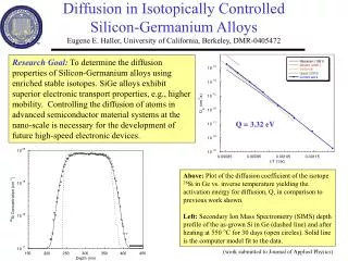
FVTX Substrate FEA. C. M. Lei March 02, 2006. Goals. To use FEA as a design tool to understand what kind of adhesives and substrate should be used for achieving a mimimal thermal displacement. Options of substrate cf/TPG/cf aluminum Options of adhesives Silicone glue (E = 2 Mpa)

FVTX Substrate FEA
E N D
Presentation Transcript
FVTX Substrate FEA C. M. Lei March 02, 2006
Goals • To use FEA as a design tool to understand what kind of adhesives and substrate should be used for achieving a mimimal thermal displacement. • Options of substrate • cf/TPG/cf • aluminum • Options of adhesives • Silicone glue (E = 2 Mpa) • Epoxy glue (E = 500 ~ 6,900 Mpa)
The Layup of the Multi-chip Module substrate
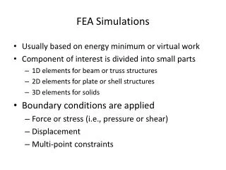
Effective Heat flux from ROC = 5.868 mW/mm^2 Effective heat flux from sensor = 0.25 mW/mm^2 Total heat load = 2.8W for half model FEA Model Half Modules with 4 chips (took advantages of symmetry and all modules evenly positioned) Cooling contact area 5mm wide at +7C Bump bond layer were modeled as a continous layer with adjusted properties based on an area ratio 21.33 (with eutectic solder bond diameter 0.035 mm assumed).
Material Library Used in this FEA Young’s modulus E, MPa Poison’s ratio n Thermal k, w/m-K CTE a, /K HDI 30e3 0.30 0.26 17e-6 Silicone glue 2 0.36 0.24 100e-6 Silicon sensor 110e3 0.30 141 2.6e-6 Silicon ROC 110e3 0.30 141 2.6e-6 Epoxy (silver filled) 500 ~ 6,900 0.36 1.59 49e-6 TPG 83e3 0.20 table -1e-6 Eutectic solder 32e3 0.051 24.7e-6 All materials were assumed to be isotropic with constant properties except - TPG in which the thermal conductivity varies - Anisotropic carbon fiber facing and bump bonds TPG Thermal K Temp in K K in W/m-K Carbon fiber 0/90facing: Einplane = 1.48e5 Mpa, Eout-of-plane =7445 Mpa, kinplane= 55.85 W/mK, kout-of-plane = 0.69 W/mK, ainplane = -0.04e-6 ppm/K, aout-of-plane=30.17e-6 ppm/K Eutectic solder bump bond layer: Ex = Ez = 0.15 Mpa, Ey = 1500 Mpa, kx = kz = 0.33e-3 W/mK, ky = 2.38 W/mK, a = 24.7e-6 ppm/K
RESULTS WITH CF/TPG/CF SUBSTRATE 0.62 mm (0.12+0.38+0.12) mm COOLING AT ENDS, 4 Combinations of Adhesives Epoxy thermal k = 1.59W/mK, cte = 49 ppm/K; silicone thermal k = 0.24W/mK, cte = 100 ppm/K Heat Load = 2.28W , Half Model with 4 chips Silicon as substrate glue Epoxy as electrical glue Overall ∆T = 19.9C From +7C to +26.9C Silicon as substrate glue Silicon as electrical glue Overall ∆T = 22.0C From +7C to +29C Epoxy as substrate glue Epoxy as electrical glue Overall ∆T = 17.9C From +7C to +24.9C Epoxy as substrate glue Silicone as electrical glue Overall ∆T = 20C From +7C to +27.0C
RESULTS WITH CF/TPG/CF SUBSTRATE 0.62 mm (0.12+0.38+0.12) mm COOLING AT ENDS SUBSTRATE GLUE IS SILICONE (E=2 Mpa ) ELECTRICAL GLUE VARIETY AS SHOWN BELOW Heat Load = 2.28W , Half Model with 4 chips E = 2 Mpa (silicon) Max resultant disp. = 3.66 microns E = 1,200 Mpa (epoxy) Max resultant disp. = 2.23 microns E = 500 Mpa (epoxy) Max resultant disp. = 2.09 microns E = 6,900 Mpa (epoxy) Max resultant disp. = 4.47 microns
RESULTS WITH CF/TPG/CF SUBSTRATE 0.62 mm (0.12+0.38+0.12) mm COOLING AT ENDS SUBSTRATE GLUE IS EPOXY (E=500 Mpa ) ELECTRICAL GLUE VARIETY AS SHOWN BELOW Heat Load = 2.28W , Half Model with 4 chips E = 2 Mpa (silicon) Max resultant disp. = 15.4 microns E = 1,200 Mpa (epoxy) Max resultant disp. = 17.4 microns E = 500 Mpa (epoxy) Max resultant disp. = 12.1 microns
RESULTS WITH ALUMINUM SUBSTRATE 1/16” (1.5875 mm) COOLING AT ENDS, 4 Combinations of Adhesives Epoxy thermal k = 1.59W/mK, cte = 49 ppm/K; silicone thermal k = 0.24W/mK, cte = 100 ppm/K Heat Load = 2.28W , Half Model with 4 chips Silicon as substrate glue Epoxy as electrical glue Overall ∆T = 17.2C From +7C to +24.2C Silicon as substrate glue Silicon as electrical glue Overall ∆T = 19.2C From +7C to +26.2C Epoxy as substrate glue Silicone as electrical glue Overall ∆T = 17.2C From +7C to +24.2C Epoxy as substrate glue Epoxy as electrical glue Overall ∆T = 15.2C From +7C to +22.2C
RESULTS WITH ALUMINUM SUBSTRATE 1/16” (1.5875 mm) COOLING AT ENDS SUBSTRATE GLUE IS SILICONE (E=2 Mpa ) ELECTRICAL GLUE VARIETY AS SHOWN BELOW Heat Load = 2.28W , Half Model with 4 chips E = 2 Mpa (silicone) Max resultant disp. = 22.2 microns E = 1,200 Mpa (epoxy) Max resultant disp. = 30.8 microns E = 500 Mpa (epoxy) Max resultant disp. = 29.9 microns
RESULTS WITH ALUMINUM SUBSTRATE 1/16” (1.5875 mm) COOLING AT ENDS SUBSTRATE GLUE IS EPOXY (E=500 Mpa ) ELECTRICAL GLUE VARIETY AS SHOWN BELOW Heat Load = 2.28W , Half Model with 4 chips E = 2 Mpa (silicone) Max resultant disp. = 29.2 microns E = 1,200 Mpa (epoxy) Max resultant disp. = 57 microns E = 500 Mpa (epoxy) Max resultant disp. = 62.3 microns
RESULTS WITH CF/TPG/CF SUBSTRATE 0.62 mm (0.12+0.38+0.12) mm
RESULTS WITH ALUMINUM SUBSTRATE 1/16” (1.5875 mm) Displacements higher than those of cf/TPG/cf substrate
Quick Conclusions • Cf/TPG/cf substrate performed better with less thermal displacement • Silicone glue should be used for the thermal substrate. • Basically any epoxy can be used for the electrically conductive adhesive, but flexible one with lower modulus is preferred.
Material Selections • Carbon fiber facing – 2 plies,0o and 90o Bryte K139-BT250, 55 gsm, 0.12 mm thick • TPG – 0.38 mm thick • Substrate adhesive – NEE001 silicone glue • Module adhesive – MasterBond MB21 TDXSFL. (Minimum order is 20 grams @ $25 per gram. If too costly, can use Tra-duct 2902 which is currently being used at Sidet and has a higher thermal conductivity at 2.99 W/mK.) More plots follow based on these selections.
RESULTS WITH CF/TPG/CF SUBSTRATE 0.62 mm (0.12+0.38+0.12) mm COOLING AT ENDS Substrate Glue: Silicone; Module Glue: 500 Mpa Epoxy Heat Load = 2.28W , Half Model with 4 chips Overall ∆T = 19.9C From +7C to +26.9C Mid-section all layers Overall ∆T = 8.3C From +18.6C to +26.9C TPG HDI sensor 19.7C 22.0C 26.9C 26.5C ∆T, sensor/ROC = 3.3C From +23.6C to +26.9C ∆T across HDI (from 22C to 26,5C) = 4.5C
OK! RESULTS WITH CF/TPG/CF SUBSTRATE 0.62 mm (0.12+0.38+0.12) mm COOLING AT ENDS Substrate Glue: Silicone; Module Glue: 500 Mpa Epoxy Heat Load = 2.28W , Half Model with 4 chips Stress Z Plot (out-of-plane 900direction) TPG Layer Max Resultant Stress = 0.9 Mpa Max Stress_Z = 0.1 Mpa Flexural Strenth = 36.7 Mpa Z = 38.5 Mpa // Tensile Strength < 0.69 Mpa Z = 6,897 Mpa //
OK! RESULTS WITH CF/TPG/CF SUBSTRATE 0.62 mm (0.12+0.38+0.12) mm COOLING AT ENDS Substrate Glue: Silicone; Module Glue: 500 Mpa Epoxy Heat Load = 2.28W , Half Model with 4 chips Stress Z Plot (out-of-plane 900direction) Carbon Fiber Layer Max Resultant Stress = 0.7 Mpa Max Stress_Z = 0.2 Mpa Flexural Strenth = 669 Mpa 00 Tensile Strength =1950 Mpa 00 = 28 Mpa 900
OK! RESULTS WITH CF/TPG/CF SUBSTRATE 0.62 mm (0.12+0.38+0.12) mm COOLING AT ENDS Substrate Glue: Silicone; Module Glue: 500 Mpa Epoxy Heat Load = 2.28W , Half Model with 4 chips Silicone Glue Layer between HDI and Substrate (E = 2 Mpa) Max Stress = 0.02 Mpa Strength_NEE001 = 1.1 Mpa
OK! RESULTS WITH CF/TPG/CF SUBSTRATE 0.62 mm (0.12+0.38+0.12) mm COOLING AT ENDS Substrate Glue: Silicone; Module Glue: 500 Mpa Epoxy Heat Load = 2.28W , Half Model with 4 chips HDI Layer Max Stress = 4.5 Mpa Tensile Strength_Kapton = 166 Mpa Tensile Strength_Copper = 320 MPa
OK! RESULTS WITH CF/TPG/CF SUBSTRATE 0.62 mm (0.12+0.38+0.12) mm COOLING AT ENDS Substrate Glue: Silicone; Module Glue: 500 Mpa Epoxy Heat Load = 2.28W , Half Model with 4 chips Module Glue Layer (E = 500 Mpa) Max Stress = 0.6 Mpa Shear Strength_MB21 TDCSFL = 6 Mpa
OK! RESULTS WITH CF/TPG/CF SUBSTRATE 0.62 mm (0.12+0.38+0.12) mm COOLING AT ENDS Substrate Glue: Silicone; Module Glue: 500 Mpa Epoxy Heat Load = 2.28W , Half Model with 4 chips Sensor and ROC Layers Max Stress = 2.4 Mpa Strength_Si = 120 MPa
OK! RESULTS WITH CF/TPG/CF SUBSTRATE 0.62 mm (0.12+0.38+0.12) mm COOLING AT ENDS Substrate Glue: Silicone; Module Glue: 500 Mpa Epoxy Heat Load = 2.28W , Half Model with 4 chips Bump Bond Layer Max Stress = 0.34*21.33 = 7.2 MPa Strength of eutect solder Tensile Yield = 43 Mpa Ultimate = 52 MPa
RESULTS WITH CF/TPG/CF SUBSTRATE 0.62 mm (0.12+0.38+0.12) mm COOLING AT ENDS, POWER OUTAGE Substrate Glue: Silicone; Module Glue: 500 Mpa Epoxy Heat Load = 2.28W , Half Model with 4 chips When heat load = 0, Temperature everywhere at +7C Max resultant disp. = 42.2 microns
OK! RESULTS WITH CF/TPG/CF SUBSTRATE 0.62 mm (0.12+0.38+0.12) mm COOLING AT ENDS, POWER OUTAGE Substrate Glue: Silicone; Module Glue: 500 Mpa Epoxy Heat Load = 2.28W , Half Model with 4 chips TPG Layer Max Resultant Stress = 7.5 Mpa Max Stress_Z = 0.56 Mpa Flexural Strenth = 36.7 Mpa Z = 38.5 Mpa // Tensile Strength < 0.69 Mpa Z = 6,897 Mpa // Stress Z Plot (out-of-plane 900direction)
OK! RESULTS WITH CF/TPG/CF SUBSTRATE 0.62 mm (0.12+0.38+0.12) mm COOLING AT ENDS, POWER OUTAGE Substrate Glue: Silicone; Module Glue: 500 Mpa Epoxy Heat Load = 2.28W , Half Model with 4 chips Carbon Fiber Layer Max Resultant Stress = 6.2 Mpa Max Stress_Z = 1.1 Mpa Flexural Strenth = 669 Mpa 00 Tensile Strength =1950 Mpa 00 = 28 Mpa 900 Stress Z Plot (out-of-plane 900direction)
OK! RESULTS WITH CF/TPG/CF SUBSTRATE 0.62 mm (0.12+0.38+0.12) mm COOLING AT ENDS, POWER OUTAGE Substrate Glue: Silicone; Module Glue: 500 Mpa Epoxy Heat Load = 2.28W , Half Model with 4 chips Silicone Glue Layer between HDI and Substrate (E = 2 Mpa) Max Stress = 0.07 Mpa Strength_NEE001 = 1.1 Mpa
OK! RESULTS WITH CF/TPG/CF SUBSTRATE 0.62 mm (0.12+0.38+0.12) mm COOLING AT ENDS, POWER OUTAGE Substrate Glue: Silicone; Module Glue: 500 Mpa Epoxy Heat Load = 2.28W , Half Model with 4 chips HDI Layer Max Stress = 6.8 Mpa Tensile Strength_Kapton = 166 Mpa Tensile Strength_Copper = 320 MPa
RESULTS WITH CF/TPG/CF SUBSTRATE 0.62 mm (0.12+0.38+0.12) mm COOLING AT ENDS, POWER OUTAGE Substrate Glue: Silicone; Module Glue: 500 Mpa Epoxy OK! Heat Load = 2.28W , Half Model with 4 chips Module Glue Layer (E = 500 Mpa) Max Stress = 2.1 Mpa Shear Strength_MB21 TDCSFL = 6 Mpa
OK! RESULTS WITH CF/TPG/CF SUBSTRATE 0.62 mm (0.12+0.38+0.12) mm COOLING AT ENDS, POWER OUTAGE Substrate Glue: Silicone; Module Glue: 500 Mpa Epoxy Heat Load = 2.28W , Half Model with 4 chips Sensor and ROC Layers Max Stress = 10.4 Mpa Strength_Si = 120 MPa
RESULTS WITH CF/TPG/CF SUBSTRATE 0.62 mm (0.12+0.38+0.12) mm COOLING AT ENDS, POWER OUTAGE Substrate Glue: Silicone; Module Glue: 500 Mpa Epoxy Could fail at corners locally Heat Load = 2.28W , Half Model with 4 chips Resultant stress at corner = 0.97*21.33 = 20.7 Mpa…OK Resultant stress in most area = 0.030*21.33 = 0.64 Mpa…OK Resultant stress in most area = 0.006*21.33 = 0.13 Mpa…OK Bump Bond Layer Strength of eutect solder Tensile Yield = 43 Mpa Ultimate = 52 MPa Max resultant stress = 3.04*21.33 = 64.8 Mpa