FEA Simulations
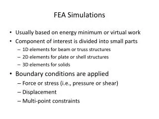
FEA Simulations. Usually based on energy minimum or virtual work Component of interest is divided into small parts 1D elements for beam or truss structures 2D elements for plate or shell structures 3D elements for solids Boundary conditions are applied

FEA Simulations
E N D
Presentation Transcript
FEA Simulations • Usually based on energy minimum or virtual work • Component of interest is divided into small parts • 1D elements for beam or truss structures • 2D elements for plate or shell structures • 3D elements for solids • Boundary conditions are applied • Force or stress (i.e., pressure or shear) • Displacement • Multi-point constraints
FEA Simulations (Contintued) • Solution of governing equations • Static: solution of simulataneous equations • Vibrations: eigenvalue analysis • Transient: Numerically step through time • Nonlinear: includes buckling uses an iterative solution • Evaluation of stress and strain • Post-processing: e.g., contour or history plots
Principal of Virtual Work Change in energy for a “virtual” displacement, , in the structure of volume, V , with surface, S, is where is the energy change is the virtual displacement is the internal stress is the virtual strain due to are the body forces (e.g., gravity, centrifugal) are surface tractions(e.g., pressure, friction) are point loads
Principal of Virtual Work (continued) The principal of virtual work must hold for all possible virtual displacements. We must convert at the nodes to in the elements. For example if we have a beam we can take and or is the strain displacement matrix.
Energy Minimization Let where U is the internal energy and Vis the potential energy due to the loads and are given by and . Recall then and and the variation becomes . Since , and , is the same as virtual work.
Finite Elements • Assume displacements inside an element is a linear (or quadratic) function of the displacements of the nodes of each element. • Assume the function outside each element is zero. • Add the displacements of each element to get the displacements of all nodes.
Finite Elements (continued) For example: For element 1: For element 2: Hence
Interpolation Function • Isoparametric elements have same function displacements as the coordinates • Transform to an element with coordinates at nodes
Interpolation Function (continued) • 2D isoparametric element • 1D isoparametric element • 3D isoparametric element in a similar manner
Volume Integration • For the parallelepiped the the shaded area is • The volume is - i.e. a determinant • For a rectangular parallelepiped • The volume is
Volume Integration (continued) • Using the isoparametric coordinates • Use similar expressions for • The volume becomes
Gaussian Quadrature • Numerical integration is more efficient if both the multiplying factor and the location of the integration points are specified by the integration rule. • The rule for integration along x can be expanded to include y and z. • For example, in one dimension, let • Transform to isoparametric coordinates and
Gaussian Quadrature (continued) • Then the integral becomes • We can write the integral as
Governing Equations • Use virtual work or energy minimization • Sum over each element since each element has no influence outside its boundary • Let where is the vector of nodal displacements for element k • Then the strains are
Governing Equations (continued) • Then • Let • And • Hence
Boundary Conditions • Surface forces have been included • So far the FE model is not restrained from rigid body motion • Hence displacement boundary conditions are needed • Recall • Let the displacement constraints be • Develop an augmented energy
Boundary Conditions (continued) • The energy minimum • Leads to
Summary • The governing equations are based on virtual work or the minimization of energy. • Displacement functions are zero outside elements. • Isoparametric elements use the same function for the coordinates and displacements inside elements • A Jacobian is required to complete integrations over the internal coordinates. • Gaussian quadrature is typically used for integrations. Hence stresses and strains are calculated at integration points. • Enforced displacements can be included through the use of Lagrange multipliers.