19.4.4 Design Example
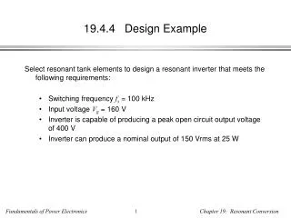
19.4.4 Design Example. Select resonant tank elements to design a resonant inverter that meets the following requirements: Switching frequency f s = 100 kHz Input voltage V g = 160 V Inverter is capable of producing a peak open circuit output voltage of 400 V

19.4.4 Design Example
E N D
Presentation Transcript
19.4.4 Design Example • Select resonant tank elements to design a resonant inverter that meets the following requirements: • Switching frequency fs = 100 kHz • Input voltage Vg = 160 V • Inverter is capable of producing a peak open circuit output voltage of 400 V • Inverter can produce a nominal output of 150 Vrms at 25 W
Preliminary calculations • The requirements imply that the inverter tank circuit have an open-circuit transfer function of: The required short-circuit current can be found by solving the elliptical output characteristic for Isc: hence Use the requirements to evaluate the above:
Matched load • Matched load therefore occurs at the operating point Hence the tank should be designed such that its output impedance is
Solving for the tank elements • Let’s design an LCC tank network for this example The impedances of the series and shunt branches can be represented by the reactances
Analysis in terms of Xs and Xp • The transfer function is given by the voltage divider equation: The output impedance is given by the parallel combination: Solve for Xs and Xp:
Evaluate tank element values • The capacitance Cp should therefore be chosen as follows: The reactance of the series branch should be
DiscussionChoice of series branch elements • The series branch is comprised of two elements L and Cs, but there is only one design parameter: Xs = 733 Ω. Hence, there is an additional degree of freedom, and one of the elements can be arbitrarily chosen. • This occurs because the requirements are specified at only one operating frequency. Any choice of L and Cs, that satisfies Xs = 733 Ω will meet the requirements, but the behavior at switching frequencies other than 100 kHz will differ. • Given a choice for Cs, L must be chosen according to: For example, Cs = 3Cp = 3.2 nF leads to L = 1.96 µH
Rcrit • For the LCC tank network chosen, Rcrit is determined by the parameters of the output ellipse, i.e., by the specification of Vg, Voc, and Isc. Note that Zo is equal to jXp. One can find the following expression for Rcrit: Since Zo0 and H are determined uniquely by the operating point requirements, then Rcrit is also. Other, more complex tank circuits may have more degrees of freedom that allow Rcrit to be independently chosen. Evaluation of the above equation leads to Rcrit = 1466 Ω. Hence ZVS for R < 1466 Ω, and the nominal operating point with R = 900 Ω has ZVS.