Download
1 / 19
240 likes | 536 Vues
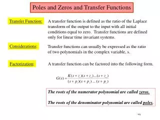
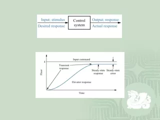
Frequency Response and Filter Design By Poles and Zeros Positioning. Dr. Mohamed Bingabr University of Central Oklahoma Slides For Lathi’s Textbook Provided by Dr. P. Cheung. Frequency Response of a LTI System.

E N D
Frequency Response and Filter Design By Poles and Zeros Positioning Dr. Mohamed Bingabr University of Central Oklahoma Slides For Lathi’s Textbook Provided by Dr. P. Cheung
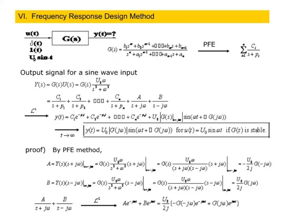
Frequency Response of a LTI System • We have seen that LTI system response to x(t)=est is H(s)est. We represent such input-output pair as: • Instead of using a complex frequency, let us set s = j, this yields: • It is often better to express H(j) in polar form: • Therefore Frequency Response Phase Response Amplitude Response
h(t) = 3e-5t |H(s)|
Frequency Response Example (1) • Find the frequency response of a system with transfer function: • Then find the system response y(t) for input x(t)=cos2t and x(t)=cos(10t-50) • Substitute s=j
Frequency Response Example (3) • For input x(t)=cos2t, we have: • Therefore
Frequency Response Example (4) • For input x(t)=cos(10t-50), we will use the amplitude and phase response curves directly: • Therefore
Frequency Response of delay of T sec • H(s) of an ideal T sec delay is: • Therefore • That is, delaying a signal by T has no effect on its amplitude. • It results in a linear phase shift (with frequency), and a gradient of –T. • The quantity: • is known as Group Delay.
Frequency Response of an ideal differentiator • H(s) of an ideal differentiator is: • Therefore • This agrees with: • That’s why differentiator is not a nice component to work with – it amplifies high frequency component (i.e. noise!).
Frequency Response of an ideal integrator • H(s) of an ideal integrator is: • Therefore • This agrees with: • That’s why integrator is a nice component to work with – it suppresses high frequency component (i.e. noise!).
Effects of Poles & Zeros on Frequency Response (1) • Consider a general system transfer function: • The value of the transfer function at some complex frequency s = p is:
Effects of Poles & Zeros on Frequency Response (2) • Therefore the magnitude and phase at s = p are given by:
Effects of Poles & Zeros on Frequency Response (3) • Frequency Response of a system is obtained by evaluating H(s) along the y-axis (i.e. taking all value of s=j). • Consider the effect of two complex system poles on the frequency response. Near to a pole ENHANCES amplitude
Effects of Poles & Zeros on Frequency Response (4) • Consider the effect of two complex system zeros on the frequency response. Near to a zero SUPPRESSES amplitude
Poles & Low-pass Filters • Use the enhancement and suppression properties of poles & zeros to design filters. • Low-pass filter (LPF) has maximum gain at =0, and the gain decreases with . • Simplest LPF has a single pole on real axis, say at (s=-c). Then • To have a “brickwall” type of LPF (i.e. very sharp cut-off), we need a WALL OF POLE as shown, the more poles we get, the sharper the cut-off. jc x x N = 2 x x x x x x 0 Re x x x x x -jc x ChebyshevFilter Butterworth Filter
Poles & Band-pass Filter • Band-pass filter has gain enhanced over the entire passband, but suppressed elsewhere. • For a passband centred around 0, we need lots of poles opposite the imaginary axis in front of the passband centre at 0.
Notch Filter • Notch filter could in theory be realised with two zeros placed at ±j0. However, such a filter would not have unity gain at zero frequency, and the notch will not be sharp. • To obtain a good notch filter, put two poles close to the two zeros on the semicircle as shown. Since both pole/zero pair are equal-distance to the origin, the gain at zero frequency is exactly one. Same for =±.
Notch Filter Example • Design a second-order notch filter to suppress 60 Hz hum in a radio receiver. • Make 0 =120. Place zeros are at s = ±j0 , and poles at - 0 cos ± j0 sin. • We get: HW7_Ch4: 4.8-1(a,b), 4.8-2 (a,b,d), 4.10-1, 4.10-3, 4.10-5, 4.10-8, 4.10-9