Chapter 8 Internet Protocol (IP)
Chapter 8 Internet Protocol (IP). Mi-Jung Choi Dept. of Computer Science and Engineering mjchoi@postech.ac.kr. Contents . 8.1 DATAGRAM 8.2 FRAGMENTATION 8.3 OPTIONS 8.4 CHECKSUM 8.5 IP PACKAGE 8.6 KEY TERMS 8.7 SUMMARY. Objectives. Upon completion you will be able to:


Chapter 8 Internet Protocol (IP)
E N D
Presentation Transcript
Chapter 8 Internet Protocol (IP) Mi-Jung Choi Dept. of Computer Science and Engineering mjchoi@postech.ac.kr
Contents 8.1 DATAGRAM 8.2 FRAGMENTATION 8.3 OPTIONS 8.4 CHECKSUM 8.5 IP PACKAGE 8.6 KEY TERMS 8.7 SUMMARY
Objectives • Upon completion you will be able to: • Understand the format and fields of a datagram • Understand the need for fragmentation and the fields involved • Understand the options available in an IP datagram • Be able to perform a checksum calculation • Understand the components and interactions of an IP package
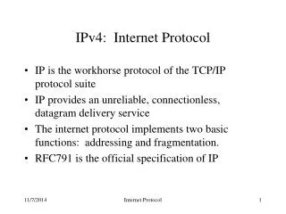
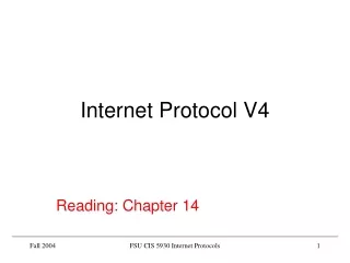
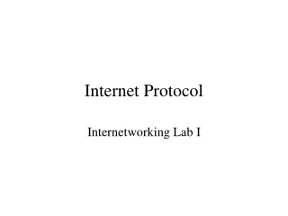
Internet Protocol (IP) • Packet delivery mechanism in TCP/IP • Unreliable connectionless datagram protocol • Each datagram handled independently • Each datagram can follow a different route to destination. • datagrams sent by same source and destination could arrive out of order • Best effort delivery • No error checking or tracking
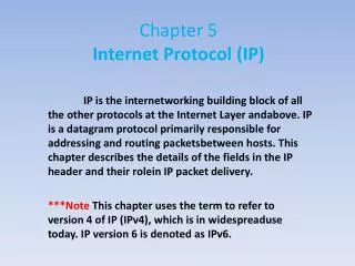
8.1 IP Datagram A packet in the IP layer is called a datagram, a variable-length packet consisting of two parts: header and data. The header is 20 to 60 bytes in length and contains information essential to routing and delivery
8.1 DATAGRAM • Version(VER) • 4BIT field • Currently, the version is 4 • Header Length(HLEN) • 4BIT field • The total length of the datagram header in 4byte words • No options : 5(5*4=20), with maximum option size : 15(15*4=60)
8.1 DATAGRAM • Differentiated Services (formerly Service Type): 8bits 1. Service type • The first 3bit : precedence bit • Precedence • 1(000) to 7(111) • The priority of the datagram (congestion) • Not used in version 4 000 routine 001 Priority 010 Immediate 011 Flash 100 Flash override 101 Critical 110 Internetwork control 111 Network control • TOS Bits Description • 0000 Normal (default) • 0001 Minimize cost • 0010 Maximize reliability • 0100 Maximize throughput • 1000 Minimize delay • The precedence subfield was designed, but never used in version 4.
Protocol TOS Bits Description ICMP 0000 Normal BOOTP 0000 Normal NNTP 0001 Minimize cost IGP 0010 Maximize reliability SNMP 0010 Maximize reliability TELNET 1000 Minimize delay FTP (data) 0100 Maximize throughput FTP (control) 1000 Minimize delay TFTP 1000 Minimize delay SMTP (command) 1000 Minimize delay SMTP (data) 0100 Maximize throughput DNS (UDP query) 1000 Minimize delay DNS (TCP query) 0000 Normal DNS (zone) 0100 Maximize throughput Table 8.2 Default types of service
Category Codepoint Assignment Authority 1 XXXXX0 Internet 2 XXXX11 Local 3 XXXX01 Temporary or experimental 8.1 DATAGRAM 2. Differentiated Services • First 6bit : code point • Last 2bit : not used • The codepoint subfield can be used in two different ways • When the 3bit right-most bits are 0s, the 3bit left-most bits are interpreted the same as the precedence bits in the Service Type Interpretation • When the 3bit right-most bits are not all 0s, the 6bits define 64 services based on the priority assignment
8.1 DATAGRAM (cont.) • Total length • The total length field defines the total length of the datagram including the header. • Total length of the IP datagram in byte(header + data) • Length of data = total length – HLEN • Maximum size : 65535 bytes (216 – 1) • Encapsulation is needed to transfer datagram in some case (some padding added)
8.1 DATAGRAM (cont.) • Identification • Used in fragmentation • Flags. • Used in fragmentation • Fragmentation offset • Used in fragmentation fragmentation
8.1 DATAGRAM (cont.) • Time to live • Datagram should have a limited lifetime • Decremented by each visited router • Discarded when zero • All the machine must have synchronized clocks and how long it takes for a datagram to go from one machine to another • Cases • Corrupted router • Intentionally limit the journey of the packet 25 25 24 24 23 22 23
Value Protocol 1 ICMP 2 IGMP 6 TCP 8 EGP 17 UDP 41 IPv6 89 OSPF 8.1 DATAGRAM(cont.) • Protocol • Define the higher level protocol that uses the services of the IP layer. • Encapsulate data from several higher level protocol(TCP,UDP,ICMP,IGMP) • Specify the final destination protocol to which datagram should be delivered
8.1 DATAGRAM (cont.) • Checksum • Later present • Source IP address • Define the IP address of the source • Destination IP address • Define the IP address of the destination
Example 1 : An IP packet has arrived with the first 8 bits as shown: 01000010 The receiver discards the packet. Why? There is an error in this packet. The 4 left-most bits (0100) show the version, which is correct. The next 4 bits (0010) show the header length, which means (2 4 = 8), which is wrong. The minimum number of bytes in the header must be 20. The packet has been corrupted in transmission. Example 2 : In an IP packet, the value of HLEN is 1000 in binary. How many bytes of options are being carried by this packet? The HLEN value is 8, which means the total number of bytes in the header is 8 4 or 32 bytes. The first 20 bytes are the main header, the next 12 bytes are the options. 8.1 DATAGRAM (cont.)
8.1 DATAGRAM (cont.) • Example 3 : In an IP packet, the value of HLEN is 516 and the value of the total length field is 002816. How many bytes of data are being carried by this packet? • The HLEN value is 5, which means the total number of bytes in the header is 5 4 or 20 bytes (no options). The total length is 40 bytes, which means the packet is carrying 20 bytes of data (40-20). • Example 4 : An IP packet has arrived with the first few hexadecimal digits as shown below: 45000028000100000102................... • How many hops can this packet travel before being dropped? The data belong to what upper layer protocol? • To find the time-to-live field, we should skip 8 bytes (16 hexadecimal digits). The time-to-live field is the ninth byte, which is 01. This means the packet can travel only one hop. The protocol field is the next byte (02), which means that the upper layer protocol is IGMP.
Ethernet formatted frame Token ring formatted frame router Ethernet network Token ring network 8.2 FRAGMENTATION • The format and size of a frame depend on the protocol used by the physical network. A datagram may have to be fragmented to fit the protocol regulations. • The topics discussed in this section include: • Maximum Transfer Unit (MTU) • Fields Related to Fragmentation
8.2 FRAGMENTATION • Maximum Transfer Unit(MTU) • Maximum size of the data field • The total size of encapsulated datagram in a frame must be less than maximum size • Differ from one physical network protocol to another IP datagram
8.2 FRAGMENTATION Table 8.5 MTUs for some networks - MTUs for different network -
8.2 FRAGMENTATION • Fragmentation • Divide the datagram to make it possible to pass some networks • Each fragment has its own header • With most of the fields repeated, but some changed • A datagram can be fragmented several times • Only final destination can reassembly of the datagram • Required parts of the header must be copied by all fragments • Three fields(flags, fragmentation offsets, total length) changed
8.2 FRAGMENTATION • Fields related to fragmentation • Identification(16bits) • Identify a datagram originating from the source host • Combination of the identification and source IP address must be unique • IP protocol uses positive number counter(guarantee uniqueness) • Kept in the Main Memory • All fragment of a datagram have the same identification number
8.2 FRAGMENTATION • Flags (3bits) • First bit : reserved • Second bit : do not fragment • 1 : must not fragment the datagram • If cannot pass the datagram through any physical network, discards the datagram and return ICMP error message to source host • 0 : the datagram can be fragmented if necessary • Third bit : more fragment • 1 : more fragments after this one • 0 : last or only fragment
8.2 FRAGMENTATION • Fragmentation offset (13bits) • Relative position of fragment with respect to the whole datagram • Offset of the data in the original datagram measured in units of eight bytes (The size of first fragment is divisible by eight) • Reassemble step in final destination host: • First fragment offset value is 0. • Divide the length of 1st fragment by 8. This value is the offset value of 2nd fragment. • Divide the length of 2st fragment by 8. This value is the offset value of 3rd fragment. • Continue the process. The last fragment has more bit value of 0.
8.2 FRAGMENTATION (cont.) Fragmentation example
Example 5 : A packet has arrived with anM bit value of 0. Is this the first fragment, the last fragment, or a middle fragment? Do we know if the packet was fragmented? If the M bit is 0, it means that there are no more fragments; the fragment is the last one. However, we cannot say if the original packet was fragmented or not. A nonfragmented packet is considered the last fragment. Example 6 : A packet has arrived with an M bit value of 1. Is this the first fragment, the last fragment, or a middle fragment? Do we know if the packet was fragmented? If the M bit is 1, it means that there is at least one more fragment. This fragment can be the first one or a middle one, but not the last one. We don’t know if it is the first one or a middle one; we need more information (the value of the fragmentation offset). However, we can definitely say the original packet has been fragmented because the M bit value is 1. 8.2 FRAGMENTATION (cont.)
Example 7 :A packet has arrived with an M bit value of1 and a fragmentation offset value of zero. Is this the first fragment, the last fragment, or a middle fragment? Because the M bit is 1, it is either the first fragment or a middle one. Because the offset value is 0, it is the first fragment. Example 8 : A packet has arrived in which the offset value is 100. What is the number of the first byte? Do we know the number of the last byte? To find the number of the first byte, we multiply the offset value by 8. This means that the first byte number is 800. We cannot determine the number of the last byte unless we know the length of the data. Example 9 : A packet has arrived in which the offset value is 100, the value of HLEN is 5 and the value of the total length field is 100. What is the number of the first byte and the last byte? The first byte number is 100 8 = 800. The total length is 100 bytes and the header length is 20 bytes (5 4), which means that there are 80 bytes in this datagram. If the first byte number is 800, the last byte number must 879. 8.2 FRAGMENTATION (cont.)
8.3 Options • The header of the IP datagram is made of two parts: a fixed part and a variable part. The variable part comprises the options that can be a maximum of 40 bytes. • The topics discussed in this section include: • Format • Option Types
8.3 OPTIONS • Security, Source routing, Record route, Timestamp • Used for network testing and debugging • Not required for every datagram • TLV(Type, Length, Value) Format
8.3 OPTIONS • Code (8bits) : Type • Copy(1bit) • Control the presence of the option in fragmentation • 0 : only copied to the first fragment • 1 : coped to all fragments • Class(2bits) • General purpose of the option • 00 : datagram control • 10 : debugging and management(01& 11 not defined) • Number(5bits) • Type of the option(only six types are in use) • Length • Total length of the option(including code and length fields) • Not present in all of the option types • Data : Value • The data that specific options require • Not present in all of the option types
8.3 OPTIONS • Option types(6 types) • Two types • 1 byte • Do not require the length or the the data fields • Four types • Multiple bytes • Require the length and the data fields
8.3 OPTIONS (cont.) • No Operation (00001) • 1 byte option • Used as a filler between options
8.3 OPTIONS (cont.) • End of Option (00000) • 1 byte option • Used for padding at the end of the option field • Only one end of option can be used • Search payload(data) after option
8.3 OPTIONS (cont.) • 경로 기록 - Record Route (00111) • Used to record the internet routers that handle the datagram • Nine router IP can be contained(4byte×9 = 36 bytes ≤ 40bytes) • Uses a pointer field containing the byte number of the first empty entry • Initialized by 4 and increased by 4 until over the length value
8.3 OPTIONS (cont.) • Strict Source Route (01001) • Used by the source to predetermine a rout for the datagram • All of the routers defined in the option must be visited by datagram • If the datagram visits a router that is not on the list, the datagram is discarded and an error message is issued • If the datagram arrives at the destination and some of the entries were not visited, it is also discarded and an error message issued
8.3 OPTIONS (cont.) Strict source route concept
8.3 OPTIONS (cont.) • Loose Source Route (00011) • Similar to the strict source route • Each router in the list must be visited, but the datagram can visit other routers
8.3 OPTIONS(cont.) • Timestamp (00101) • Used to record the time of datagram processing by a router • Milliseconds from midnight, Universal Time • Overflow field • Records the number of routers that could not add their timestamp because of no more fields available • Flags field • Specify the visited router responsibilities
8.3 OPTIONS (cont.) Use of flag in timestamp • 0 : add only the timestamp in the provided field • 1 : add each router’s outgoing IP address and the timestamp • 3 : each router must check the given IP address with its own incoming IP address • If matched, the router overwrites the IP address with its outgoing IP address and • adds the timestamp
8.3 OPTIONS (cont.) Timestamp concept
Example 10:Which of the six options must be copied to each fragment? We look at the first (left-most) bit of the code for each option. No operation: Code is 00000001; no copy. End of option: Code is 00000000; no copy. Record route: Code is 00000111; no copy. Strict source route: Code is 10001001; copied. Loose source route: Code is 10000011; copied. Timestamp: Code is 01000100; no copy. Example 11 : Which of the six options are used for datagram control and which are used for debugging and management? We look at the second and third (left-most) bits of the code. No operation: Code is 00000001; control. End of option: Code is 00000000; control. Record route: Code is 00000111; control. Strict source route: Code is 10001001; control. Loose source route: Code is 10000011; control. Timestamp: Code is 01000100; debugging 8.3 OPTIONS (cont.)
Example 12 One of the utilities available in UNIX to check the travelling of the IP packets is ping. In the next chapter, we talk about the ping program in more detail. In this example, we want to show how to use the program to see if a host is available. We ping a server at De Anza College named fhda.edu. The result shows that the IP address of the host is 153.18.8.1. $ ping fhda.eduPING fhda.edu (153.18.8.1) 56(84) bytes of data.64 bytes from tiptoe.fhda.edu (153.18.8.1): .... The result shows the IP address of the host and the number of bytes used.
Example 13 We can also use the ping utility with the -R option to implement the record route option. $ ping -R fhda.eduPING fhda.edu (153.18.8.1) 56(124) bytes of data.64 bytes from tiptoe.fhda.edu (153.18.8.1): icmp_seq=0 ttl=62 time=2.70 msRR: voyager.deanza.fhda.edu (153.18.17.11) Dcore_G0_3-69.fhda.edu (153.18.251.3) Dbackup_V13.fhda.edu (153.18.191.249) tiptoe.fhda.edu (153.18.8.1) Dbackup_V62.fhda.edu (153.18.251.34) Dcore_G0_1-6.fhda.edu (153.18.31.254) voyager.deanza.fhda.edu (153.18.17.11) The result shows the interfaces and IP addresses.
Example 14 The traceroute utility can also be used to keep track of the route of a packet. $ traceroute fhda.edutraceroute to fhda.edu (153.18.8.1), 30 hops max, 38 byte packets 1 Dcore_G0_1-6.fhda.edu (153.18.31.254) 0.972 ms 0.902 ms 0.881 ms 2 Dbackup_V69.fhda.edu (153.18.251.4) 2.113 ms 1.996 ms 2.059 ms 3 tiptoe.fhda.edu (153.18.8.1) 1.791 ms 1.741 ms 1.751 ms The result shows the three routers visited.
Example 15 The traceroute program can be used to implement loose source routing. The -g option allows us to define the routers to be visited, from the source to destination. The following shows how we can send a packet to the fhda.edu server with the requirement that the packet visit the router 153.18.251.4. $ traceroute -g 153.18.251.4 fhda.edu. traceroute to fhda.edu (153.18.8.1), 30 hops max, 46 byte packets 1 Dcore_G0_1-6.fhda.edu (153.18.31.254) 0.976 ms 0.906 ms 0.889 ms 2 Dbackup_V69.fhda.edu (153.18.251.4) 2.168 ms 2.148 ms 2.037 ms
Example 16 The traceroute program can also be used to implement strict source routing. The -G option forces the packet to visit the routers defined in the command line. The following shows how we can send a packet to the fhda.edu server and force the packet to visit only the router 153.18.251.4, not any other one. $ traceroute -G 153.18.251.4 fhda.edu. traceroute to fhda.edu (153.18.8.1), 30 hops max, 46 byte packets 1 Dbackup_V69.fhda.edu (153.18.251.4) 2.168 ms 2.148 ms 2.037 ms
8.4 CheckSum • The error detection method used by most TCP/IP protocols is called the checksum. The checksum protects against the corruption that may occur during the transmission of a packet. It is redundant information added to the packet. • The topics discussed in this section include: • Checksum Calculation at the Sender • Checksum Calculation at the Receiver • Checksum in the IP Packet
8.4 CheckSum in IP • To create the checksum, the sender does the following: 1. The packet is divided into k sections, each of n bits. 2. All sections are added together using one’s complement arithmetic. 3. The final result is complemented to make the checksum. • Checksum in one’s complement arithmetic