Comprehensive Guide to Internet Protocol (IP) and Its Services
Explore the fundamentals of IP, its header fields, and services it offers to upper layer protocols, with a focus on packet delivery and routing. Learn about IP version 4 (IPv4) and its essential role in internetworking.

Comprehensive Guide to Internet Protocol (IP) and Its Services
E N D
Presentation Transcript
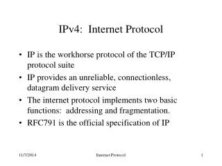
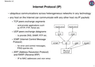
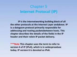
Chapter 5Internet Protocol (IP) IP is the internetworking building block of all the other protocols at the Internet Layer andabove. IP is a datagram protocol primarily responsible for addressing and routing packetsbetweenhosts. This chapter describes the details of the fields in the IP header and their roleinIP packet delivery. ***Note This chapter uses the term to refer to version 4 of IP (IPv4), which is in widespreadusetoday. IP version 6 is denoted as IPv6.
Introduction to IP IP is the primary protocol for the Internet Layer of the Department of Defense (DoD) Advanced Research Projects Agency (DARPA) model and provides the internetworking functionality that makes large-scale internetworks such as the Internet possible. IP has lasted since it was formalized in 1981 with RFC 791 and will continue to be used on the Internet for years to come. Only relatively recently have IP’s shortcomings been addressed in a new version known as IPv6. For more information about IPv6, see Chapter 8, “Internet Protocol Version 6 (IPv6).” IP’s amazing longevity is a tribute to its original design.
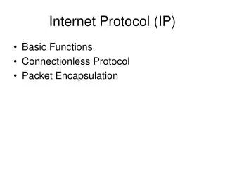
IP Services IP offers the following services to upper layer protocols: ■ Internetworking protocol ■ Multiple client protocols ■ Datagram delivery ■ Independence from Network Interface Layer At the Internet Layer ■ Fragmentation and reassembly To support the maximum frame sizes of different Network Interface Layer technologies ■ Extensible through IP options When features are required that are not available using the standard IP header ■ Datagram packet-switching technology
ตาราง 5-1 IP MTUs for Common Network Interface Layer Technologies IP MTU
The IP Datagram รูปที่ 5-1 โครงสร้างของ IP datagram Network Interface layer
The IP Header Figure 5-2 shows the IP header’s structure. The following sections discuss the fields of the IP header.
Version The Version field is 4 bits long and is used to indicate the IP header version. A 4-bit field can have values from 0 through 15. The most prevalent IP version used today on organization intranets and the Internet is version 4, sometimes referred to as IPv4. The next version of IP is IPv6. All other values for the Version field are either undefined or not in use. For the latest list of the defined values of the IP Version field, see http://www.iana.org/assignments/version-numbers.
Internet Header Length The Internet Header Length (IHL) field is 4 bits long and is used to indicate the IP header size. The maximum number that can be represented with 4 bits is 15. Therefore, the IHL field cannot possibly be a byte counter. Rather, the IHL field indicates the number of 32-bit words (4-byte blocks) in the IP header. The typical IP header does not contain any options and is 20bytes long. The smallest possible IHL value is 5 (0x5). With the maximum amount of IPoptions, the largest IP header can be 60 bytes long, indicated with a IHL value of 15 (0xF). Using a 4-byte block counter to indicate the IP header size means that the IP header size must always be a multiple of 4. If a set of IP options extend the IP header, they must do so in 4-byte increments. If the set of IP options is not a multiple of 4 bytes long, option padding bytes must be used so that the IP header an each option is always on a 4-byte boundary.
Type Of Service Figure 5-3 The structure of the RFC 791 IP Type Of Service field
Precedence The Precedence field is 3 bits long and is used to indicate the importance of the datagram. Table 5-2 lists the defined values of the Precedence field.
Delay The Delay field is a flag indicating either Normal Delay (when set to 0) or Low Delay (when set to 1). If Delay is set to 1, the IP router forwards the IP datagram along the path that has the lowest delay characteristics. An application can request the low delay path when sending either time-sensitive data, such as digitized voice or video, or interactive traffic, such as Telnet sessions. Based on the Delay flag, the router might choose the lower delay terrestrial wide area network (WAN) link over the higher delay satellite link, even if the satellite link has a higher bandwidth.
Throughput The Throughput field is a flag indicating either Normal Throughput (when set to 0) or High Throughput (when set to 1). If the Throughput field is set to 1, the IP router forwards the IP datagram along the path that has the highest throughput characteristics. An application can request the high throughput path when sending bulk data. Based on the Throughput flag, the router can choose the higher throughput satellite link over the lower throughput terrestrial WAN link, even if the terrestrial link has a lower delay.
Reliability The Reliability field is a flag indicating either Normal Reliability (when set to 0) or High Reliability(when set to 1). During periods of congestion at an IP router, the Reliability field is used to decide which IP datagrams to discard first. If the Reliability field is set to 1, the IP routerdiscardsthese datagrams last. An application can request the high reliability path when sending time-sensitive data, so that it cannot be discarded. For example, with some methods of sending digital video, the digitized video is sent as two types of packets: The primary type is used to reconstruct the basic video image, and a secondary type is used to provide a higher resolution image. In this case, the primary packets are sent with the Reliability field set to 1 and the secondary packets are sent with the Reliability field set to 0. If congestion occurs at the router, the router discards the secondary packets first.
Cost The Cost field is a flag indicating either Normal Cost (when set to 0) or Low Cost (when set to 1), where cost indicates monetary cost. If the Cost field is set to 1, the IP router forwards the IP datagram along the path that has the lowest cost characteristics. An application can request the low cost path when sending noncritical data. Based on the Cost flag, the router can choose a lower cost terrestrial link over a higher cost satellite link, even if the terrestrial link has a lower bandwidth.
Reserved The Reserved field is the last bit and must be set to 0. Routers ignore this field when forwarding IP datagrams.
RFC 2474 Definition of the TOS Field Figure 5-4 The structure of the RFC 2474 IP TOS field
Explicit Congestion Notification and the TOS Field designers of TCP/IP created a new set of standards for both hosts and routers. These standards describe active queue management (AQM) on IP routers (RFC 2309) to allow the router to monitor that state of its forwarding queues and provide a mechanism to enable routers to report to sending hosts that congestion is occurring, allowing the sending hosts to lower their transmission rate before the router begins dropping packets. The router reporting and host response mechanism is known as Explicit Congestion Notification (ECN) and is defined in RFC 3168. ECN support in IP uses the two unused bits of the RFC 2474-defined TOS field. Figure 5-5 shows the new definition of the TOS field with ECN.
Figure 5-5 The structure of the RFC 3168 IP TOS field The two unused bits in the RFC 2474-defined TOS field are defined in RFC 3168 as the ECN field, which has the following values: ■ 00 The sending host does not support ECN. ■ 01 or 10 The sending host supports ECN. ■ 11 Congestion has been experienced by a router.
Total Length As Figure 5-2 shows, the Total Length field is 2 bytes long and is used to indicate the size of the IP datagram (IP header and IP payload) in bytes. With 16 bits, the maximum total length that can be indicated is 65,535 bytes. For typical maximum-sized IP datagrams, the total length is the same as the IP MTU for that Network Interface Layer technology. Between the header length and the total length, the IP payload length can be determined from the following formula: IP payload length (bytes) = Total Length value (bytes) – (4 × IHL value (32-bit words))
Identification The Identification field is 2 bytes long and is used to identify a specific IP packet sent between a source and destination node. The sending host sets the field’s value, and the field is incremented for successive IP datagrams. The Identification field is used to identify the fragments of an original IP datagram.
Flags The Flags field is 3 bits long and contains two flags for fragmentation. One flag is used to indicate whether the IP payload is eligible for fragmentation, and the other indicates whether or not there are more fragments to follow for this fragmented IP datagram. More information on these flags and their uses can be found in the section titled “Fragmentation,” later in this chapter.
Fragment Offset The Fragment Offset field is 13 bits long and is used to indicate the offset of where this fragment begins relative to the original unfragmented IP payload. More information on the Fragment Offset field can be found in the section titled “Fragmentation,” later in this chapter.
Time-To-Live The Time-To-Live (TTL) field is 1 byte long and is used to indicate how many links on which this IP datagram can travel before an IP router discards it. The TTL field was originally intended for use as a time counter, to indicate the number of seconds that the IP datagram could exist on the Internet. An IP router was intended to keep track of the time that it received the IP datagram and the time that it forwarded the IP datagram. The TTL was then decreased by the number of seconds that the packet resided at the router. However, the latest modern standard (RFC 1812) specifies that IP routers decrement the TTL by 1 when forwarding an IP datagram. Therefore, the TTL is an inverse link count. The sending host sets the initial TTL, which acts as a maximum link count. The maximum value limits the number of links on which the datagram can travel and prevents a datagram from indefinitely looping.
Protocol The Protocol field is 1 byte long and is used to indicate the upper layer protocol containedwithinthe IP payload. Some common values of the IP Protocol field are 1 for ICMP, 6 for TCP,and17 (0x11) for UDP. The Protocol field acts as a multiplex identifier so that the payload can be passed to the proper upper layer protocol on receipt at the destination node. Windows Sockets applications can refer to protocols by name. Protocol names are resolved to protocol numbers through the Protocol file stored in the %SystemRoot%\System32 \Drivers\Etc directory. Table 5-3 lists some of the values of the IP Protocol field for protocols that Windows Server 2008 and Windows Vista support.
Table 5-3 Values of the IP Protocol Field For a complete list of IP Protocol field values, see http://www.iana.org/assignments/protocol-numbers.
Header Checksum The Header Checksum field is 2 bytes long and performs a bit-level integrity check on the IP header only. The IP payload is not included, and IP payloads must include their own checksums to check for bit-level integrity. The sending host performs an initial checksum in the sent IP datagram. Each router in the path between the source and destination verifies the Header Checksum field before processing the packet. If the verification fails, the router silently discards the IP datagram. Because each router in the path between the source and destination decrements the TTL, the header checksum changes at each router.
Source Address The Source Address field is 4 bytes long and contains the IP address of the source host, unless a network address translator (NAT) is translating the IP datagram. A NAT is used to translate between public and private addresses when connecting to the Internet. NAT is defined in RFC 1631.
Destination Address The Destination Address field is 4 bytes long and contains the IP address of the destination host, unless the IP datagram is being translated by a NAT or being loose-or strict-source routed. More information on IP source routing can be found in the section titled “IP Options,” later in this chapter.
Options and Padding Options and padding can be added to the IP header, but must be done in 4-byte increments so that the size of the IP header can be indicated using the Header Length field. For an example of the structure of the IP header, the following is frame 1 of Capture 05-01, a Network Monitor trace that is included in the \Captures folder on the companion CD-ROM, as displayed with Network Monitor 3.1:
Fragmentation When a source host or a router must transmit an IP datagram on a link and the MTU of the link is less than the IP datagram’s size, the IP datagram must be fragmented. When IP fragmentation occurs, the IP payload is segmented and each segment is sent with its own IP header. The IP header contains information required to reassemble the original IP payload at the destination host. Because IP is a datagram packet-switching technology and the fragments can arrive in a different order from which they were sent, the fragments must be grouped (using the Identification field), sequenced (using the Fragment Offset field), and delimited (using the More Fragments flag).
Fragmentation Fields Figure 5-6 shows the fragmentation fields in the IP header, which are described in the following sections.
Figure 5-6 The fields in the IP header used for fragmentation
Identification The IP Identification field is used to group all the fragments of the payload of an original IP datagram together. The sending host sets the value of the Identification field, and this value is not changed during the fragmentation process. The Identification field is set even when fragmentation of the IP payload is not allowed by setting the Don’t Fragment (DF) flag.
Don’t Fragment Flag The DF flag is set to 0 to allow fragmentation and set to 1 to prohibit fragmentation, so fragmentation occurs only if the DF flag is set to 0. If fragmentation is needed to forward the IP datagram and the DF flag is set to 1, the router should send an ICMP Destination Unreachable-Fragmentation Needed And DF Set message back to the source host and discards the IP datagram. Fragmentation and reassembly is an expensive process at the routers and the destination host. The DF flag and the ICMP Destination Unreachable-Fragmentation Needed And DF Set message are the mechanisms by which a sending host discovers the MTU of the path between the source and the destination, or Path MTU Discovery. For more information, see Chapter 6,“Internet Control Message Protocol (ICMP).”
More Fragments Flag The More Fragments (MF) flag is set to 0 if there are no more fragments that follow this fragment (this is the last fragment), and set to 1 if there are more fragments that follow this fragment (this is not the last fragment).
Fragment Offset The Fragment Offset field is set to indicate the position of the fragment relative to the original IP payload. The Fragment Offset is an offset used for sequencing during reassembly, putting the incoming fragments in proper order to reconstruct the original payload. The Fragment Offset field is 13 bits long. With a maximum IP payload size of 65,515 bytes (the maximum IP MTU of 65,535 minus a minimum-sized IP header of 20 bytes), the Fragment Offset field cannot possibly indicate a byte offset. At 13 bits, the maximum value is 8191. The fragment offset must be 16 bits long to be a byte offset.
Fragmentation Example As an example of the fragmentation process, a node on a Token Ring network sends a fragmentable IP datagram with the IP Identification field set to 9999 to a node on an Ethernet network, as shown in Figure 5-7.
Figure 5-7 An example of a network where IP fragmentation can occur
Assuming a 9-ms token holding time, a 4-Mbps ring, and no Token Ring source routing header, the IP MTU for the Token Ring network is 4482 bytes. The Ethernet IP MTU is 1500 bytes using Ethernet II encapsulation. Table 5-4 shows the fields relevant to fragmentation in the IP header and their values for the original IP datagram. Table 5-4 Original IP Datagram
Figure 5-8 The IP fragmentation process when fragmenting from a 4482-byte IP MTU link to a 1500-byte IP MTU link
Table 5-5 shows the fields relevant to fragmentation in the IP header of the four fragments.
Reassembly Example The fragments are forwarded by the intermediate IP router(s) to the destination host. Because IP is a datagram-based packet-switching technology, the fragments can take different paths to the destination and arrive in a different order from which the fragmenting router forwarded them. IP uses the Identification and Source IP Address fields to group the arriving fragments together. After receiving a fragment (not necessarily the first fragment of the original IP payload), an IP implementation can allocate reassembly resources comprised of the following:
■ A data buffer to contain the IP payload (65,515 bytes) ■ A header buffer to contain the IP header (60 bytes) ■ A fragment block bit table (1024 bytes or 8192 bits) ■ A total length data variable ■ A timer
Figure 5-9 The IP reassembly process for the four fragments of the original IP datagram
Fragmenting a Fragment It is possible for fragments to become further fragmented. In this case, each fragmented payload is fragmented to fit the MTU of the link onto which it is being forwarded. The process of fragmenting a fragmented payload is slightly different from fragmenting an original IP payload in how the MF flag is set. When fragmenting a previously fragmented payload, the MF flag is always set to 1, except when the fragment of the fragmented payload is the last fragment of the original payload.
Avoiding Fragmentation Although fragmentation allows IP nodes to communicate regardless of differing MTUs in intermediate subnets and without user intervention, IP fragmentation and reassembly is a relatively expensive process—both at the routers (or sending hosts) and at the destination host. On the modern Internet, fragmentation is highly discouraged; Internet routers are busy enough with the forwarding of IP traffic.
Setting the DF Flag with Ping The Windows Server 2008 and Windows Vista Ping.exe tool with the -f option can be used to set the DF flag to 1 in ICMP Echo messages. The syntax is ping –f Destination For example, to ping 10.0.0.1 and set the DF flag to 1, use the following command: ping -f 10.0.0.1 By default, ICMP Echo messages sent by the Ping.exe tool have the DF flag set to 0 (fragmentation allowed).