Download
1 / 21
210 likes | 379 Vues
Digital backend system for Usuda 64-m station. Hiroshi Takeuchi (ISAS/JAXA) & Kazuhiro Takefuji (NICT). Outline. Specification of the DBE Related software development DBE signal monitor & controller, format translator

E N D
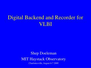
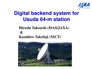
Digital backend system for Usuda 64-m station Hiroshi Takeuchi (ISAS/JAXA) & Kazuhiro Takefuji (NICT)
Outline • Specification of the DBE • Related software developmentDBE signal monitor & controller, format translator • On-going mission supports with the DBEDelta-DOR(IKAROS, Akatsuki, Standardization) Open-loop recorder(IKAROS)Radio astronomy(Radio astron, Pulsar) • Future mission supports with the DBEHayabusa-2, Bepi-Colombo, Mars aero capture
Applications of the DBE at the Usuda64m station • Delta Differential One-way Ranging (DDOR) 100kHz bw(Spacecraft) 2-4MHz(Quasar) • Open-loop receiver (2-4MHz bw, 4-8bit quantization) • Radio astronomy (16-32MHz bw ) • Pulsar observation (256-1024MHz bw, Quantization 4-8 bits, single channel) • Geodetic VLBI (2-8MHz bw x 16ch) High flexibility required to meet these various kinds of requirements
Signal flow at Usuda 64-m station K5/VSI system RCP RCP RCP RCP X-Band RF to IF Down converter ADS-3000+ LCP LCP LCP LCP A/D converter Down converter PC (data storage, system control, post processing & data transfer) C-Band RF to IF Down converter Down converter VSI-H A/D converter . . . IF Distributor Selector A/D converter S-Band RF to IF Down converter Down converter A/D converter L-Band RF to IF Down converter IF:500MHz
Schematic diagram of the DBE VSI-H port1 64MHz(2048Mbps) VSI-H port2 64MHz(2048Mbps) DBBC output mode:16ch,4 or 2bit Baseband bandwidth:4, 8, 16, 32MHz Wideband output mode: 1ch Bandwidth:64,128,256,512,1024,2048MHz IF Input(IF bandwidthDC~2GHz) Trade-off between sampling rate and number of channels. 4ch(1028 Msps×8bit) 2ch(2048 Msps×8bit) 1ch(4096 Msps×8bit)
Output modes of the DBE Output bandwidth 4~ 2048MHz /ch Software based BBC IFsignal 512,1024,2048MHz 25kHz/ch~200kHz/ch 8,16 bit resolution PC DBE ADS-3000+
Algorithm of the DDBC I CIC Decimation Filter Decimation rate 16,32,64,128 Compensation FIR Filter (65tap ) Selector I/Q orReal(USB/LSB) cosφ From ADC 1024Mbps/8 bit output 8,16,32,64Msps/4bit NCO -sinφ Q • Output bandwidth and NCO phase can be changed in real-time synchronized with 1pps • (e.g. 512-MHz of wideband output for quasar & 4MHz of DBBC output for each tone of Spacecraft signals) • NCO phase can be modeled with 3rd order of polynomial function→ Easy to detect the weak carrier signal.
Input & Output signal monitorDC offset/Gain controller Histogram Time-series raw data IF-Signal VSI ADS-3000+ RAID PC recorder Ethernet Spectrum Monitor/control PC
Format translator DBE ADS-3000+ VDIF (VLBI stations) Delta-DOR Raw-data Exchange Format (Space agencies) K5 format (JAXA,NICT,GSI) Real (USB,LSB) from/to Complex(I/Q) software converter Mark5 LBA(ATNF) ESU format(ESA) VSR format(JPL) Real sampling (USB/LSB) Complex sampling
Header section Record representing 1 second of observation Data section Data Standardized raw data exchange format for Delta-DOR • Developing standardized raw data exchange format at the CCSDS(Consultative Committee for Space Data Systems) Delta-DOR WG(ESA,JPL,JAXA). • Will be published in Spring 2013. Observation mode 1kHz 16bit~16MHz 1bit
On-going mission supports: Delta-DOR for the Planet-C(Venus orbiter) Joint observation between JAXA & JPL Achieved precision: 700[psec]
On-going mission supports: Delta-DOR for the IKAROS(Solarsail demonstrator) UTAS: Hobart26m ATNF: Mopra 22m, ATCA 22m CSIRO/DSN: DSS34 34m,DSS45 34m, DSS43 70m ESA: Cebreros 35m New Norcia 35m SHAO:Urumqi 25m, Shanghai 25m,Kunming40m NICT: Kashima34m GSI: Tsukuba32m JAXA: UDSC64m USC34m The first-ever solar sail spacecraft launched in 2010. Epuipped with a wideband DOR tone generator
Measurement accuracy of the IKAROS Delta-DORexperiment Achieved accuracy(thermal noise level) was 50 ps level. →10-times improved accuracy compared to the Planet-C →Almost same level as the JPL’s Delta-DOR system 2010/7/29USUDA – Canberra baseline Quasar delay of BL Lac VLBI delay( nano second) Quasar delay of J1425-2513 Delta-DOR observable(-7.83ns±50ps) IKAROS Delay Time from the start of the observation(second)
Rescue observations for the IKAROS Due to the very high spin rate, it became impossible to track the IKAROS with conventional PLL receiver from November 2011.
Carrier phase measurements with the DBE (Open-loop receiver) Receive frequency was modeled every 10miniutes as : Carrier frequency is fitted to this equation every 10 minutes with 6-dimentional non-linear least-squares method
2-way Doppler observables are measured for Orbit determination
IKAROS was found after 8 monthsabsence on Sep. 6, 2012. • The IKAROS was confirmed to be shut down its onboard equipment due to low power generation on Jan. 6, 2012. • On Sept. 6, 2012, carrier signal emitted from the IKAROS was found by using this carrier detection method.
Future missions which need Delta-DOR • HAYABUSA-2 (Approved. Launch date: 2014 or 2015)Sample-return mission to the C-type asteroid 1999 JU3. (Artificial Crater formation by impactor.)VLBI contributes to developing precise ephemeris of the target asteroid. Detecting Yarkovsky effect (Orbit perturbation by anisotropic emission of thermal photons from the surface of the asteroid) may be able to be measured.
Future mission: Mercury orbiter Bepi-Colombo(Launched in 2014, Mercury orbit insertion in 2020) Joint mission between ESA and JAXA MMO(JAXA) MPO(ESA) Cruising phase: Two-time Venus swing-by &Four-time mercury swing-by→ VLBI tracking supporting request from ESA. Orbiter phase: Same-beam VLBI of both spacecrafts. ESA Bulletin Vol103 ,pp.11-19 ,R. Grard