Download
1 / 16
160 likes | 190 Vues
This document provides information on the low voltage power requirements for TOF Front-end Electronics (FEEs), including maximum power, low noise characteristics, floating outputs, and independent supplies per tray. It also discusses the safety measures, rack configuration, and cost considerations.

E N D
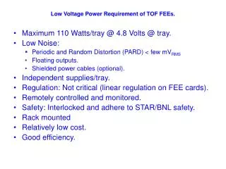
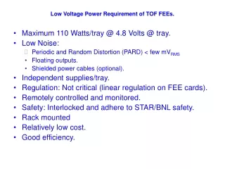
Low Voltage Power Requirement of TOF FEEs. • Maximum 110 Watts/tray @ 4.8 Volts @ tray. • Low Noise: • Periodic and Random Distortion (PARD) < few mVRMS • Floating outputs. • Shielded power cables (optional). • Independent supplies/tray. • Regulation: Not critical (linear regulation on FEE cards). • Remotely controlled and monitored. • Safety: Interlocked and adhere to STAR/BNL safety. • Rack mounted • Relatively low cost. • Good efficiency.
LV Electrical Connection Details crimp lug connector AMP 52042-1 P<110 watts
LV power Supply Arrangement in the Full size Racks • Total power dissipated by each tray ~ 110 Watts • Total Power dissipated outside power supply [55 Watts dissipated in each transmission cable] (trays + cables) ~ 165 Watts • Total heat dissipation per output channel (assuming 83% efficiency) ~ 34 Watts • Total Heat Dissipation per power supply mainframe (12 outputs) ~ 408 Watts • Total heat dissipation per full rack (6 x PL508 or PL512) ~ 2.45 KW • Available cooling power/rack (3 heat exchangers) ~ 3.6 KW A full rack supplies power to 72 trays Max. input power per PL512 chasis: 3 KW (power factor 0.96; Vmax = 208 V; Imax=15 A) http://www.wiener-d.com/products/20/73.html
Comparison of Various Power Supply Choices The estimated costs per channel do not include rack costs (if one includes the additional costs then switching power supply costs are the lowest) 12 supplies/3U >24 racks 9 racks 2 racks
Details of Low Voltage Supply Connections Cable lengths vary: 80’ -100’
Power Supply Noise Characteristics Load: 100 A @ 5 Volts
Comparison of Noise Rates in TOF5:Linear Supply vs. Wiener PL508
TOF System Resolution from Off-Line AnalaysisKepco Linear (red curve) vs. Wiener (blue curve)(March 2005 Cu-Cu)
Slow Control for the TOF Low Voltage System Ethernet This figure shows tray power supplies only. There is an additional power supply mainframe for the Start detector FEEs and TDIG boards (and a few spares).
TOF High Voltage System Requirements. • High Voltage to provide symmetric HV up to +/- 7.5 KV @ few uA/tray (this current takes into account Beam on condition scaled to RHIC upgrade luminosities). • Remote programability/monitoring: Voltage, current limits, ramping rates, voltage and current monitoring (10 nA resolution). • Isolation: power supply outputs must be floating. Furthermore, since one set of plus and minus outputs supply current for up to 10 trays tray inputs are isolated from other trauys to avoid interference. • HV will be interfaced to STAR interlock system. • Remote control software will be based on EPICS (or LabView) and will be interfaced to STAR controls (logging and alarms).
Choice of HV Power Supply. • CAEN SY127 mainframe with A631 pods has been used to supply HV to MRPCs (some problems have been encountered during last two runs - failed A631 modules). • Each SY127 accommodates 10 A631 pods. Each A631 pod (negative and positive output versions available) supplies 4 independent floating channels. Each output could supply up to 8 KV at 100 uA. (One fully equipped SY127 would serve the entire TOF system). Output current limited internally and also by external limiting resistors located @ distribution boxes. • Distribution boxes located on the magnet will fan out each pair of + and – HV to up to 10 trays. These boxes will supply required isolation, filtering, current limiting and grounding of the HV (see figure on the next page). • CPE Italia SPA (rated ~20 KV) cables (HV RG-58) will be used for HV distribution.These cables have been flame tested by Phenix Collaboration. • Kings (or Reynolds equivalent) ) 1065 series 10 KV (DC tested to 25 KV) will be used to interface the HV to power supplies, distribution boxes, and the trays. (The new Reynolds equivalent connectors are rated at 15 KV @ approximately the same cost). • Remote control and monitoring of the SY127 will be done through CAENET (PC based A1303 PCI-HS CAENET controller already used to control HV system in the past few years).
High Voltage System CAEN SY127 HV Supply Chassis [one of two required units shown]
LabView GUI for SMD TCP/IP-based HV Control Program for CAEN SY1527 Mainframe Developed by UCLA.
Arrangement of Supplies in Half Height Racks. Linear Regulated Supplies Total of 30 racks required Ferroresonant power supply Total of 8 racks required Wiener power supply Total of 3 racks required