Download

1 / 13
130 likes | 169 Vues
Explore the concept of pipelined datapaths in computer architecture, including timing assumptions, instruction formats, and pipelined computer architectures. Learn about the benefits and principles of pipelining in processing data efficiently.

E N D
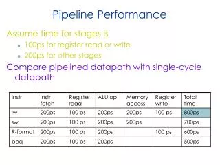
Lecture 15:Pipelined Datapath Soon Tee Teoh CS 147
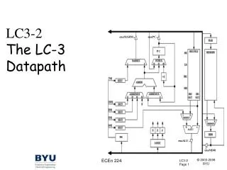
Control and Datapath (Figure 9-15, page 471) Extend V C N Z Branch Control PC D Register File A B RW DA AA Address Instruction Memory Instruction P J B L B C BA Constant in Zero fill Instruction Decoder 1 0 MUX B MB MW D B A M F M R M P J B A A A B S D W W L B C FS V C N Z A B Function Unit F Data in Address Data Memory Data Out 0 1 MUX D MD
Instructions in this Architecture Instruction Format Description Add RD, RA, RB R[DR] R[SA] + R[SB] OR RD, RA, RB R[DR] R[SA] v R[SB] Shift Right RD, RB R[DR] sr R[SB] Load Immediate RD, OP R[DR] zf OP Load RD, RA R[DR] M[SA] Store RD, RA M[SA] R[SB] Branch on Zero RA, AD if (R[SA]==0) PC PC + se AD Jump RA PC R[SA] • zf means zero-fill • se means sign-extend • sr means shift right
Timing Assumptions • Branch Control: 1ns • PC Read: 1ns • PC Write: 2ns • Instruction Memory Read: 3ns • Instruction Decoder: 1ns • Extend: 1ns • Zero Fill: 1ns • Register File Read: 1ns • Register File Write: 2ns • 2-to-1 MUX: 1ns • Function Unit: 6ns • Memory Read: 3ns • Memory Write: 3ns Note: “Register File Read” refers to the propagation delay time of a register. “Register File Write” refers to the set-up time of a register.
Delay for each component in Control and Datapath Extend V C N Z 2ns 2ns Branch Control 1ns PC D Register File A B 1ns RW DA AA 1ns Address Instruction Memory Instruction P J B L B C BA 3ns 1ns 1ns Constant in Zero fill 1ns 1ns Instruction Decoder 1 0 MUX B MB MW 3ns D B A M F M R M P J B A A A B S D W W L B C FS V C N Z A B Function Unit F Data in Address Data Memory Data Out 6ns 3ns 0 1 MUX D 1ns MD
Time taken in Longest Path Extend V C N Z 2ns 2ns Branch Control 1ns PC D Register File A B 1ns RW DA AA 1ns Address Instruction Memory Instruction P J B L B C * BA 3ns 1ns 1ns Constant in Zero fill 1ns 1ns Instruction Decoder 1 0 MUX B MB MW 3ns D B A M F M R M P J B A A A B S D W W L B C FS V C N Z A B Function Unit F Data in Address Data Memory Data Out 6ns * 3ns 0 1 MUX D Total time for ADD instruction = 1 + 3 + 1 + 1 + 1 + 6 + 1 + 2 = 16ns 1ns MD
Pipelining Concept • Separate laundry process into 3 steps wash/rinse/dry. Each step uses a different machine. • Suppose you have many loads. • While first load is drying, second load is rinsing, and first load is washing. • Simultaneously utilizing all resources. • Like Henry Ford’s assembly line
Pipelined Computer Architecture • Separate the process into separate parts • For our example, we separate into 4 parts: • 1. Instruction Fetch • 2. Decode, Operand Fetch • 3. Execute • 4. Write Back • Insert new registers between each stage to hold some control signals
PC IF IF DOF DOF EX EX WB WB Pipelined Computer (Figure 11-4 pg 550, ignore branch control for now) Read Address Instruction Memory Instruction Register File A B Write BA AA registers/ memory IR Zero fill Instruction Decoder Read/ Write 1 0 MUX B MB registers B A M A A B Address Data Memory Data Out FS A B Function Unit F FS MW MW Data In Address Data Memory 0 1 MUX D DA MD RW MD D Register File RW DA Stages: Instruction Fetch, Decode/Operand Fetch, Execute, Write Back
PC IF IF DOF DOF EX EX WB WB Timing in Pipelined Computer (assume register read is 1ns and register write is 1ns) Read Address Instruction Memory Instruction Register File A B 5ns Write BA AA registers/ memory IR Zero fill Instruction Decoder Read/ Write 1 0 MUX B MB 5ns registers B A M A A B Address Data Memory Data Out FS A B Function Unit F FS MW 8ns MW Data In Address Data Memory 0 1 MUX D 4ns DA MD RW MD D Register File RW DA Stages: Instruction Fetch, Decode/Operand Fetch, Execute, Write Back
Clock cycle time • In non-pipelined computer, clock cycle needs to be at least 16ns. Clock frequency = 1/16ns = 62.5 MHz • In pipelined computer, clock cycle needs to be at least 8ns, the time for the slowest stage. Clock frequency = 1/8ns = 125 MHz • If we need to execute 7 instructions using the non-pipelined computer, we need 7 x 16 = 112 ns. • How much time do we need using the pipelined computer?
Pipelined Computer timing 8ns 8ns 8ns 8ns 8ns 8ns 8ns 8ns 8ns 8ns IF DOF EX WB IF DOF EX WB Instruction 2 IF DOF EX WB IF DOF EX WB IF DOF EX WB IF DOF EX WB IF DOF EX WB We need 80ns. In general, # cycles needed = # instructions + # stages - 1
Pipelined Computer timing 8ns 8ns 8ns 8ns 8ns 8ns 8ns 8ns 8ns 8ns IF DOF EX WB IF DOF EX WB IF DOF EX WB IF DOF EX WB IF DOF EX WB Filling: Not all stages active IF DOF EX WB IF DOF EX WB All stages active Emptying: Not all stages active