Download
1 / 20
220 likes | 470 Vues
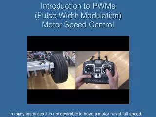
Learn about DC motors, pulse width modulation for speed control, operating principles, construction, and PWM generation methods. Explore PWM practical circuits for efficient motor speed control.

E N D
Study of DC motor and its speed control by pulse width modulation (PWM) • GuidedBy: • S. Joseph Winston SO/G & • Joel Jose • SO/D • RHS/RIRD/MMG • Indira Gandhi Centre for Atomic Research, Kalpakkam, Tamil Nadu-603102, India • Govt. of India • Submitted By: • Anand Kumar Singh • B.Tech 2nd Year/IV Sem • Department of Electrical Engineering • Enrollment No. 1413564 Giani Zail Singh Campus College Of Engineering & Technology Punjab Technical University (PTU) • Govt. of Punjab
Outlook • Objective • Introduction to DC Motor • Why Speed Control • Literature survey • PWM • Speed Control by PWM • Comparison • Conclusion
Objective • Study of DC motor • Operating principle • Speed control of DC motor by pulse width modulation (PWM)
Introduction to DC motor • A motor is a class of electrical machines that converts electrical power to mechanical power • A DC motor uses direct current for conversion of electrical energy to mechanical energy • It is also known as Permanent magnet direct current (PMDC) machine • Stator consist of a pair of fixed permanent magnets producing a uniform and stationary magnetic flux inside the motor and hence the name of “permanent-magnet direct-current” (PMDC) motors
Operating principle of DC motor • When a current carrying conductor is placed in a magnetic field it experiences a force/torque and has a tendency to move • This is known as motoring action • The magnitude of the force is given by F=ilB B:magnetic field, i:current,l:length of conductor • If the direction of current in the wire is reversed, the direction of rotation also reverses • When magnetic fieldand electric field interact they produce a mechanical force
Equivalent circuit diagram of DC motor • The equivalent circuit diagram of dc motor • The mathematical expression of voltage is given by: • Vdc= IaRa+ Ea(Using KVL) Ia: armature current Ra: armature resistance Vdc: dc supply voltage Ea : back emf Ea/Eb is back emf
Construction of DC Motor Every DC motor consist of 6 parts • Stator, field magnet, Rotor, Commutator, Field windings, Brushes
Why speed control of DC Motor is necessary • The speed of the motor should neverbe more than ratedspeed • Textile industries require a variable speed for their operation • Therefore it is necessary to control the speed of the motor by changing the magnetic flux
Literature survey • From the literature survey it has been found that speed of a DC motor can be controlled by: • 1. FLUX CONTROL: • Magnetic field depends upon current flowing through the field winding • B α I • And flux varies with field current • фα I • Current can be varied by introducing a series resistance with field winding • I α 1/R • Speed (N) α 1/ ф Demerit: Only speed above base speed can be controlled
2. ARMATURE VOLTAGE CONTROL • Insert a variable resistor (R) in series with the armature • When resistance (R) is gradually increased, the voltage across the armature decreases • and we know that • Speed of DC motor is proportional to voltage drop across the armature • N α V (N=K(V-IaRa)/ф) • Hence, the Speed of a DC motor also decreases Demerit: Huge power loss due to extra resistance
3. SUPPLY VOLTAGE CONTROL Pulse Width Modulation (PWM) • Both the above mentioned methods cannot provide speed control in the desirable range • Whereas the armature control method involves huge power loss due to its usage of resistor in series with the armature • Therefore, a different method is often desirable – the one that controls the supply voltage to control the motor speed is PWM Merit: Effective speed control in desired range
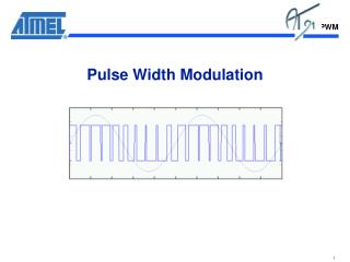
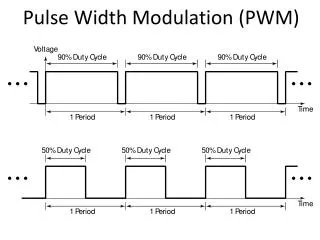
Pulse Width Modulation (PWM) • This is an effective method to control the o/p voltage with constant frequency • This is a modulation of pulses by varying the duty cycle • Duty cycle (α) is a ratio of Ton/(Ton+Toff ) • The width of pulses (T) determines the amount of avg. voltage applied to motor terminals. • Height of pulse gives Average voltage
PWM generation There are two ways to generate pulse width modulation with variable duty cycle • Using analog electronics (operational amplifier, comparator and saw tooth generator) • Using digital electronics (microprocessor and dedicated PWM controller) Practical circuit
Speed Control by PWM • Pulse Width Modulation (PWM) is a method for binary signals generation • It has 2 signal periods (high and low). • The width (W) of each pulse varies between 0 and the period (T). • The main principle is control of power by varying the duty cycle. • The average voltage at output is given by Va = α Vmax Where, α=Ton /(Ton +TOff) TON =Time period for Pulse ON,TOFF =Time period for Pulse OFF
Benefit of Pulse Width Modulation (PWM) • Power efficiency: The power efficiency is very high • Speed control behaviour: A precise speed control is achieved • Control circuit: Since it uses electronic components it is compact • Harmonics: It reduces the harmonics of output
Comparison of flux control, armature control & pulse width modulation(PWM)
Conclusion • A detailed study of DC motor has been done • Speed control of DC motor has been done by different types of speed control methods • Among these PWM wins the race • Precise control of dc motor speed can be achieved
THIS PROJECT IS DEDICATED TO MY GUIDE • S.Joseph Winston Joel Jose • SO/GSO/D