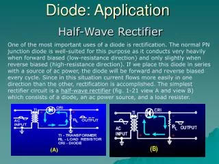
Download
1 / 16
160 likes | 194 Vues
Explore the concept of ideal diodes in non-linear circuits, covering bias regions, i-v relationships, mechanical analogs, and circuit analysis techniques. Learn why studying ideal diodes is crucial for understanding circuit behavior. Start with resistor extremes to facilitate comprehension.

E N D
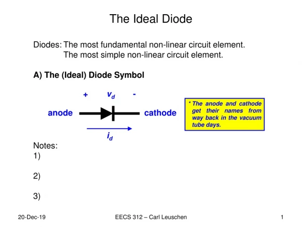
The Ideal Diode • Diodes: The most fundamental non-linear circuit element. • The most simple non-linear circuit element. • A) The (Ideal) Diode Symbol • Notes: • 1) The device is not symmetrical, we must specify (name) the connections: anode and cathode. • Positive voltage is defined from the anode to the cathode. • 3) Positive currect is defined from the anode to the cathode. + vd - * The anode and cathode get their names from way back in the vacuum tube days. anode cathode id EECS 312 – Carl Leuschen
The Ideal Diode • Q. Why do we study the “ideal” diode rather than a real diode? • An ideal diode is a close approximation to the real thing, and it is simplified (easy to understand). • Resistor Extremes (a quick review) • We are going to start easy and work our way up; but first let’s start really easy and review the resistor, specifically in the extreme cases when R=0 and R=∞. + vr - ir Area of lower resistance. INVALID (negative resistance) Area of higher resistance. ir vr Area of higher resistance. INVALID (negative resistance) Area of lower resistance. EECS 312 – Carl Leuschen
The Ideal Diode + vr - ir R=0 ir vr Short Circuit ir + vr - R=∞ ir vr Open Circuit EECS 312 – Carl Leuschen
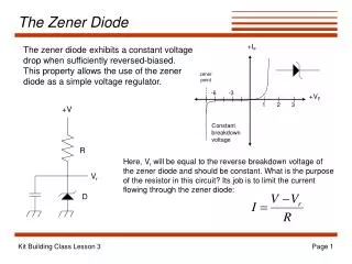
The Ideal Diode • C) The Ideal Diode Bias Regions • OK, we know that a resistor with R=0 is a short circuit (v=0) and a resistor with R=∞ is an open circuit (i=0), but what does this have to do with a diode? • The ideal diode has a “split personality.” Sometimes it wants to be a short and sometimes it wants to be an open, depending on the applied voltage and current (or bias). • When current flow is in the positve direction, the ideal diode is a short circuit or FORWARD BIASED. + vd - + vd = 0 - Current flow is in the pos. direction. id > 0 id > 0 Forward Biased: id> 0& vd = 0 SHORT CIRCUIT EECS 312 – Carl Leuschen
The Ideal Diode • C) The Ideal Diode Bias Regions (Continued) • When current tries to flow in the negative direction(negative voltage applied), the ideal diode is an open circuit or REVERSE BIASED. • The ideal diode only lets current flow in one direction. When current is flowing in the positive direction there is no resistance (arrow), and when current tries to flow in the negative direction there is infinite resistance (wall). + vd < 0 - + vd < 0 - Current is trying to flow in the neg. direction. id = 0 id Reverse Biased: vd < 0 & id= 0 OPEN CIRCUIT EECS 312 – Carl Leuschen
The Ideal Diode • D) The Ideal Diode i-v Relationship • Remember the ideal diode acts like a short when it is forward biased, id>0 (vd=0), and like an open when it is reverse biased, vd<0 (id=0). • Is ideal diode is linear? • No. • What is the power dissipated in the ideal diode? • A. Zero. id Short Circuit + vd - vd id Open Circuit EECS 312 – Carl Leuschen
The Ideal Diode D) The Ideal Diode i-v Relationship Review id Short Circuit + vd - vd id Open Circuit EECS 312 – Carl Leuschen
The Ideal Diode • E) The Ideal Diode Mechanical Analog (Continued) • An analog for the diode is a mechanical valve to control liquid flow (another could be a ratchet). • When liquid flows in the positive direction throug the valve there is no pressure difference between the two sides. • Pressure (A) – Pressure (B) = 0 • This is the short circuit analog. Infinite Source: Water Tower Side A Side B EECS 312 – Carl Leuschen
The Ideal Diode • E) The Ideal Diode Mechanical Analog • When the valve is reversed and liquid tries to flow in the negative direction through the valve, there is no flow and a pressure difference exists between the two sides. • Pressure (A) – Pressure (B) < 0 • This is the open circuit analog. Infinite Source: Water Tower Side B Side A EECS 312 – Carl Leuschen
The Ideal Diode E) The Ideal Diode Mechanical Analog (Continued) Side A Anode Side B Cathode Pressure Difference Voltage Liquid Flow Current Case 1 Forward Bias Case 2 Reverse Bias Pressure Difference Side A Side B + vd - anode cathode id EECS 312 – Carl Leuschen
The Ideal Diode • F) Circuit Analysis with the Ideal Diode • We have shown that the ideal diode can be replace by either a short circuit when it is forward biased or an open circuit when it is reverse biased. • We also know that it is easy to analyze a circuit containing an open or a short circuit; so if we know how the diode is biased, we can replace it with an open or short and solve. • But what determines how the diode is biased? • The circuit attached to it! • The Chicken and the Egg Dilemma • We need to solve the circuit to figure out how the ideal diode is biased, but we need to know how it is biased before we can solve the circuit. • There is a very elegant solution. WE GUESS. EECS 312 – Carl Leuschen
The Ideal Diode • F) Circuit Analysis with the Ideal Diode • The Five Step Guide to Analyzing Ideal Diode Circuits • 1) Assume a bias state for each diode (In other words, just GUESS). • a) ASSUME the ideal diode is forward biased (short). • b) ASSUME the ideal diode is reverse biased (open). • Since each ideal diode has two possible states; there will be n2 possible configurations, where n is the number of diodes. • Enforce the EQUALITY condition of your ASSUMPTION. • (Replace the diode with the equivalent circuit) • a) If you assumed forward bias then E.C. is vd=0. • Replace it with a short circuit. • b) If you assumed reverse bias then E.C. is id=0. • Replace it with an open circuit. EECS 312 – Carl Leuschen
The Ideal Diode • F) Circuit Analysis with the Ideal Diode • IMPORTANT!! RETAIN THE SAME VOLTAGE AND CURRENT DEFINITIONS (DIRECTIONS) WHEN YOU REPLACE THE IDEAL DIODE. + vd - Equality Condition + vd = 0 - Assume Forward Bias (Short) Current Definition id id OR + vd - + vd - Voltage Definition Assume Reverse Bias (Open) Equality Condition id = 0 id EECS 312 – Carl Leuschen
The Ideal Diode • F) Circuit Analysis with the Ideal Diode • Analyze the circuit. • Do this after you have replaced all the diodes with either short circuits or open circuits. • a) Determine all desired (required) circuit values. • - You will need these for the answer. • b) Determine id across the short circuit, and • Determine vd across the open circuit. • - You will need these to check you initial assumptions. EECS 312 – Carl Leuschen
The Ideal Diode • F) Circuit Analysis with the Ideal Diode • 4) Check if the INEQUALITY Condition of your assumption is correct. • a) An ideal diode cannot have a negative current. If you assumed forward bias then the current must be non-negative (Inequality condition is id≥ 0). • b) An ideal diode cannot have a positive voltage. If you assumed reverse bias then the voltage must be non- positive (Inequality condition is vd ≤ 0). • Bias, Short, Open, Equality Condition, Inequality Condition? • This chart is actually useful to keep track of assumption during analysis. EECS 312 – Carl Leuschen
The Ideal Diode • F) Circuit Analysis with the Ideal Diode • If the inequality conditions do not match with the analysis results then change your assumption and go back to step 2. • Hints for ideal diode circuit analysis. • 1) you must check all inequality conditions. • vd = 2.2V ≤ 0 NO … start again. • id = 1.5A ≥ 0 YES • 2) Do not check the equality conditions, check the inequality conditions. • 3) There is only one solution (set of assumptions) that will be correct. EECS 312 – Carl Leuschen