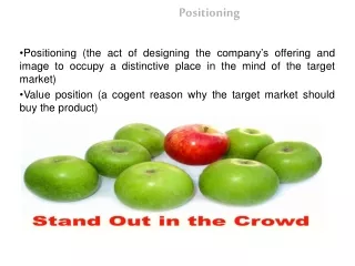
Understanding Positioning Excitation and Quality Factors in Resonator-Based Gyroscopes
This document explores the concept of positioning excitation in resonators, where electrostatic forces localize the acting force under a specific angle. It highlights the distinction between bound waves and free waves, detailing the equations governing the forces involved. A focus is placed on the Q-factor of materials used in resonator construction, comparing the Q-factors of different materials like fused quartz and stainless steel. The relationship between surface quality and resonator performance is also discussed, emphasizing the importance of material selection for achieving high gyro accuracy.

Understanding Positioning Excitation and Quality Factors in Resonator-Based Gyroscopes
E N D
Presentation Transcript
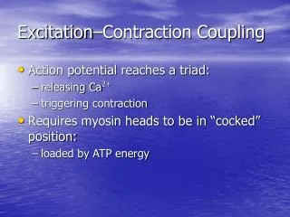
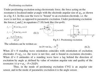
=0 V(,0) el V=Vocos(t/2) Fig.8.1. Positioning excitation. Vo o el Positioning excitation Under positioning excitation using electrostatic force, the force acting on the resonator is localized under angle with the electrode angular size of el, as shown in a fig. 8.1. In this case the wave is "bound" to an excitation electrode, i.e. the wave is not free, as opposed to parametric excitation. Under positioning excitation the forces fxand fy in equations (7.10) look like (for =0): (8.1) The solution can be written as: (8.2) When = 0 standing wave orientation coincides with orientation of excitation electrodes =el, i.e. the wave is not free, and is bound in excitation electrodes. When 0 antinodes of a standing wave have a lag behind the direction of excitation by angle , defined by value of rotation angular rate and quality of the resonator () el - 2k/. Thus, in the mode of positioning excitation CVG is an angular rate sensor, and in the mode of parametric excitation it is the angle sensor.
Material Q-factor The scale factor of Coriolis vibratory gyroscope using the second oscillation mode is determined by Q-factor of the resonator and depends first of all on a material (Q-factor of a material) from which it is made, and also processing quality of resonator surface and others less considerable parameters (for example, rotational symmetry of its geometrical shape, method of fixation, excitation etc. As an example it is possible to compare Q-factors of two hemispherical resonators with diameter of 58 mm manufactured from different materials: fused quarts, and stainless steel. Q-factors of these resonators are approximately equal to 107 and 104, respectively. Considerable influence of resonator surface quality (surface roughness, availability of microcrackes etc.) is demonstrated by the following results: the Q-factor of the resonator manufactured from fused quarts KV has increased from 0.6106 to 4.6106, i.e. almost 8 times, after chemical treatment of its surface which eliminated a defective layer of 9 microns width. The surface quality for low Q-factor’s resonators made, for example of stainless steel, is not influence on Q-factor and also gyro accuracy so much, it is estimated at the level of 10%. Thus selection of a material, from which the resonator is manufactured and processing techniques of its surface are the important stage in designing, which determines gyro accuracy grade made of high Q-factor materials.
Q-factors of different materials (at the room temperature) are represented in the table 8.1. On the basis of this table it is possible to select a material for resonator, proceeding from a desirable accuracy grade of the future gyro. Table 8.1 When selecting the proper material it is also necessary to take into account labor consumption of material processing, availability of production equipment for high-quality surface processing of the selected material etc.As can be seen from the table the greatest Q-factor has sapphire, crystalline quarts, fused quarts, beryllium. However it is necessary to take into account, that the sound losses in crystalline depends on a direction of crystal axis and, hence, usage of such materials is not expedient from a technological point of view. Technological processing simplicity and the cost of materials have resulted in that the fused quarts is now widely used material for CVG resonator. Rate integrated hemispherical resonator CVG made of fused quarts is referenced to as hemispherical resonator gyroscope (HRG).
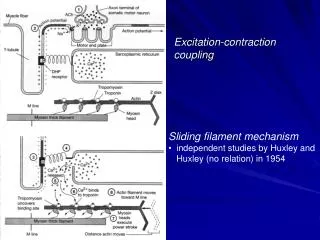
1 3 2 2 4 6 3 4 5 5 Fig. 8.3. Fig.8.2. HRG using quarts resonator with two stems and tines (a) and one stem without tines (b). For measurement of Q-factor of glasses the set-up represented in fig.8.3 can be used. The cylinder from a tested material 1 is hanged in vacuum chamber with the help of a silk thread. The ends of the cylinder are • covered with a thin conducting layer (by evaporation in vacuum). The excitation of oscillations (with amplitude of 0.1 microns) is carried out by the generator 6 and capacitive electrodes 2, and signal reads-out is carried by the capacitive pick-offs 3, amplifiers 4 and by amplitude detector 5. Voltage of 600 V is applied on excitation electrodes at the resonant frequency and after reaching prescribed oscillation amplitude the voltage is off and amplitude damping time by e2.7 times is measured. The estimated value of material Q-factor is obtained using the formula Q=/2.The principle of operation of a vibration gyroscope is similar to a principle of operation of a ring laser gyroscope. In ring laser gyro a standing electromagnetic wave is established in a closed optical resonator.
Distance between nodes of a standing electromagnetic wave is equal to half of wavelength of light. Certainly, it essentially differs from distance between nodes of an acoustic standing wave in a vibratory gyroscope, which is equal to a quarter of a circumference of the resonator. Owing to such large difference in lengths of the working waves, temperature sensitivity due to resonator length change of a vibratory gyroscope manufactured on the basis of a quartz resonator much lower, than ring laser gyroscope. Actually, the coefficient of thermal expansion of fused quarts is almost the same as a glass ceramic, from which resonator of laser gyro is manufactured, therefore, at an identical temperature variation change of the geometrical sizes of two resonators (acoustic and optical one) will be, approximately, identical. However, the relative resonator size change (relative the length of a working wave) for laser gyro will be some orders more, than for a vibratory gyroscope. As a result, the thermal drift of a vibratory gyroscope made of fused quartz is almost the order of magnitude less, than that of laser gyro.CVGs can be mechanized to operate as rate gyros in an open-loop mode or a closed-loop force-rebalance mode, or they can be mechanized to operate as rate-integrating gyros in so called whole-angle mode. In the open-loop mode, one of the vibration modes (the driven mode) is excited by a force of prescribed amplitude at resonant frequency.
Inertial rotation about the input axis then results in the excitation of the second mode (the readout or sensing mode). The vibrationamplitude of the readout-mode is proportional to the input rate. • The bandwidth of CVGs mechanized in the open-loop mode is directly related to the time it takes the readout-mode vibration to transit to its new steady-state value after a step change in input rate. In this case required bandwidth is achieved in practice either by increasing the damping, or by separating the driven-mode and readout-mode natural frequencies. Both result in accuracy decreasing. • Open-loop mode disadvantages can be eliminated by transition the CVG in to the so-called force-rebalance mode. In the force-rebalance mode, the driven mode is maintained at prescribed amplitude, but the vibration arising in the readout mode (sensing mode), as a result of inertial rotation, is driven to zero by feedback control system. The force required to null the sensing mode vibration is then proportional to the input rotation rate. • CVG can operates in the whole-angle mechanization mode. In the whole-angle mechanization mode, the Coriolis force resulting from input rotation makes the elastic wave rotates together with resonator in the same direction, but with lag angle described by coefficient k0.4 (it is called Bryan coefficient) so as gyro rotation angle is equal to =k, where is elastic wave rotation angle.
w21 45o resonator Added mass w22 Fig 8.4. Fourth harmonic in mass distribution Resonator Imperfections and CVG errors. Frequency mismatch The basic reason of CVG errors is technological errors of quartz resonator manufacturing and non-uniformity of a material. The most essential influence on CVG error has a non-uniformity of mass distribution along circumferential coordinate of the resonator, arising as a result of difference in shell thickness. • As shows a Fourier analysis of difference in hemispherical shell thickness along circumferencial coordinate, for the second working mode (n = 2), when there are four nodes and antinodes along resonator perimeter, maximum influence on CVG error has the fourth harmonic of mass distribution. As a result of availability of such defect the natural frequency of the resonator oscillations is split on two frequencies. The more the difference in resonator shell thickness the more the frequency mismatch. The fourth harmonics of mass distribution along the resonator rim gives the following value of the split frequencies: =2/2 where is a relative value of a defect on the fourth harmonics (m/m), Fig. 8.4 shows the simple distribution of a shell thickness with large component on 4-th harmonics, at which shell thickness at four equally distanced points is more, than in other points. Because the spherical shells tend to smooth the local stiffness (or elasticity), due to
the thickness variation, the basic contribution is given by the fourth harmonic of mass variation. Therefore, if the standing wave is located with its nodes along solid axes (see fig. 8.4), and the resonator is considered as a linear vibratory system of the second order, has an approximately identical elastic coefficient, but a little larger weight, the natural oscillation frequency for the wave which antinodes are established along dotted axes a little bit above, than the frequency of n = 2 mode. Two different frequencies of normal modes, each of them corresponds to particular arrangement of a standing wave results in that the standing wave is established so, that its antinodes are located somewhere in between normal axes. For determination of the resultant wave motion, it is necessary to decompose the wave on component along normal axes. As these components oscillate with different frequencies originally established standing wave ceases to be a standing wave; travelling-wave components develop. Also, it is possible to explain it that a secondary quadrature wave is created, which antinodes coincide with initial wave nodes and, oscillating with a phase quadrature relative to initial wave. The drift rate is determined by the following expression: (8.3) where o is an angle between direction of oscillations and one of the natural axes of the resonator (for example, axis with a minimum oscillation frequency), = 21-22 is the resonator natural frequency splitting. From the expression 8.3 it can be
seen, that when o = 0, /4, that is the direction of oscillations coincides with one of natural axes of the resonator, but there is not a wave drift and oscillations are represented by pure standing wave (without travelling components).It should be noted, that for the second harmonic of resonator material density defect determined by expression: =о(1+2cos2). (8.4) The estimation of resonator natural frequency splitting is determined by the expression: (8.5) As we can see from this expression the magnitude of the frequency splitting has the second order of smallness relative to the second harmonic defect. It should be noted that frequency splitting due to the first and third harmonic defects also give the magnitude of the second order of smallness. Thus, when manufacturing the resonator it is necessary to give the special notice to the fourth harmonic defect because this harmonic has much greater influence on CVG errors, than the remaining ones. Q-Factor Mismatch The other important source of a drift is the nonuniform distribution of damping sources in the resonator. As in the case of the shell-thickness variation that leads to a splitting of the second mode frequency discussed earlier, it is the fourth harmonic of the damping distribution in the circumferencial direction that produces the effect.
1 resonator о 45 Added damping 2 Fig 8.5. Fourth harmonic in damping material distribution 2 location drift drift Drift rate drift 90o 22.5o 67.5o 112.5o 0o 45o Fig.8.6. Case-Oriented drift. Fig. 8.5 is intended to be suggestive of a particularly simple damping distribution with a strong fourth-harmonic component. If the supposed damping material has the property that it develops a retarding force on the resonator proportional to the shell velocity in the radial direction, then a standing wave with its antinodes located at the places of added damping will have a lower Q ( lower time constant) than a standing wave whose nodes lie over the added damping material. To understand the nature of the standing wave drift that occurs, we decompose the standing wave into components along the two principal damping axes (the solid and dashed axes in fig. 8.5). The amplitudes of these two components damping away at rates 1/1 and 1/2, respectively. Since the ring electrode is replenishing these losses at the same rate, and the amplitude control loop is maintaining the square root of the sum of the squares of the amplitudes of the two waves at a prescribed value, the component with the lower time constant damping entirely away, and the standing wave ends up aligned with the higher time constant axes. Fig. 8.6 shows a graph of the standing wave drift as a function of pattern angle. It is sinusoidal with a peak value proportional to the difference of the reciprocals of the two time constants.