Download
1 / 26
260 likes | 411 Vues
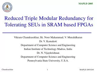
Ressource Reduced Triple Modular Redundancy for Built-In Self-Repair in VLIW-Processors. Mario Schölzel. Outline. Why Built-In Self-Repair? Base Architecture Resource Reduced TMR Program Modifications Architecture Modifications Conclusions and Limitations. Why Built-In Self-Repair ?.

E N D
Ressource Reduced Triple Modular Redundancy for Built-In Self-Repair in VLIW-Processors Mario Schölzel
Outline Motivation VLIW Architecture RR-TRM Idea SW Modifications HW Modifications Conclusion • Why Built-In Self-Repair? • Base Architecture • Resource Reduced TMR • Program Modifications • Architecture Modifications • Conclusions and Limitations
Why Built-In Self-Repair ? Motivation VLIW Architecture RR-TRM Idea SW Modifications HW Modifications Conclusion • Hardware becomes unreliable (permanent faults due to small feature size) • ITRS Roadmap 2005 for Design predicts requirement for reliable systems due to: • Infeasibility of full functional test at manufacturing exit • Relaxing 100% correctness requirement (reduces functional test complexity and cost) • Consequence: Redundancy in the system is required for robustness!
Processor 1 Processor 2 Voter Input Output Processor 3 Simple TMR-Approach Motivation VLIW Architecture RR-TRM Idea SW Modifications HW Modifications Conclusion We consider the following application domain: • High-performance signal processing applications (i.e. image- and audio-processing) • Real-Time demands
Basic Processor Architecture Program Memory Data Memory Control Path Extern Data Path Register File Control Logic ... Instruction Pointer FU n Branch FU 1 Motivation VLIW Architecture RR-TRM Idea SW Modifications HW Modifications Conclusion
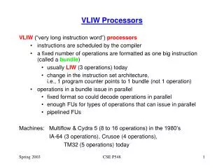
Idea of Resource Reduced TMR Motivation VLIW Architecture RR-TRM Idea SW Modifications HW Modifications Conclusion • Redundant operators are naturally available in a VLIW data path • In TMR: Three results are only necessary in case of a mismatch of two results • Idea of RR-TMR: Perform every operation only by two operators and use in non-fault case third operator for executing regular operations
Program Memory Data Memory Extern Control Path Data Path Regular Register File Control Logic ... Instruction Pointer FU n Branch FU 1 FD & C Logic FD & C Logic Voting Control Logic Temporary Register File Modified VLIW Data Path Motivation VLIW Architecture RR-TRM Idea SW Modifications HW Modifications Conclusion Limitation: Every operator must be available at least three times.
Duplicated Operations * * * * * * * * 5 : 4 : 7 : 8 : 12 : 11 : 2 : 1 : 6 :+ 9 :+ 13 :+ 3 :+ + + 10 :+ 14 :+ + * * * * 17 : 18 : 16 : 15 : + + + 20 :+ 19 :+ * * * * 24 : 23 : 21 : 22 : * * * * * * * * * * * 26 :+ 25 :+ Pair of Reference Operations 27 :+ 28 :+ Program Transformation Motivation VLIW Architecture RR-TRM Idea SW Modifications HW Modifications Conclusion
Modified Part of Instruction Word Motivation VLIW Architecture RR-TRM Idea SW Modifications HW Modifications Conclusion opcode src 1 src 2 dst mod RefREG RefFU • RefFU: number of FU that executes reference operation • Mod=0: RefReg is target register in TRF • Mod=1: RefReg delivers reference value from TRF • These fields must be set correctly for every operation and its duplicate after scheduling all operations (We allow scheduling of original and duplicate operations at different times)
Example: Instruction Word Motivation VLIW Architecture RR-TRM Idea SW Modifications HW Modifications Conclusion Result of Scheduling … FU 2 FU 3 … Time step 8 + Time step 9 Time step 10 + Corresponding Instruction Words Instruction Word Part of FU 2 Instruction Word Part of FU 3 OpC Src1 Src2 Dst mod RReg RFU OpC Src1 Src2 Dst mod RReg RFU + R3 R6 R0 0 R6 3 Instr. 8 Instr. 9 + R3 R6 R0 1 R6 2 Instr. 10
FD&C Logic Details Motivation VLIW Architecture RR-TRM Idea SW Modifications HW Modifications Conclusion Detects, if current result is faulty Every bit represents fault status of corresponding operator Decides whether an error occurs first time or not and gives a signal to Voting Logic Compares current result and reference value from register RefReg in TRF Opcode of currently executed operation in corresponding FU
Write Port of Result of Write Port of Result of FU 2 in RF FU 2 FU 3 in RF FU 3 to voting logic From voting logic to voting logic to voting logic From voting logic to voting logic Fault Fault Fault Fault errOpc errOpc Vector Vector Re - Re - mem - mem - opcode opcode ber ber i i _ _ e e F F r r r r a a o o u u RefFU RefFU r r l l t t errDet errDet mod RefReg mod RefReg Cmp Cmp Control of TRF Control of TRF Read Port Read Port Write Port Write Port Read Ports Read Ports TRF TRF TRF TRF Example: Correct Execution Motivation VLIW Architecture RR-TRM Idea SW Modifications HW Modifications Conclusion Instruction Word Part of FU 2 Instruction Word Part of FU 3 OpC Src1 Src2 Dst mod RReg RFU OpC Src1 Src2 Dst mod RReg RFU + R3 R6 R0 0 R6 3 Instr. 8 Instr. 9 + R3 R6 R0 1 R6 2 Instr. 10 0 0 0 0
Write Port of Result of Write Port of Result of FU 2 in RF FU 2 FU 3 in RF FU 3 to voting logic From voting logic to voting logic to voting logic From voting logic to voting logic Fault Fault Fault Fault errOpc errOpc Vector Vector Re - Re - mem - mem - opcode opcode ber ber i i _ _ e e F F r r r r a a o o u u RefFU RefFU r r l l t t errDet errDet mod RefReg mod RefReg Cmp Cmp Control of TRF Control of TRF Read Port Read Port Write Port Write Port Read Ports Read Ports TRF TRF TRF TRF Example: FU 2 is Faulty Motivation VLIW Architecture RR-TRM Idea SW Modifications HW Modifications Conclusion Instruction Word Part of FU 2 Instruction Word Part of FU 3 OpC Src1 Src2 Dst mod RReg RFU OpC Src1 Src2 Dst mod RReg RFU + R3 R6 R0 0 R6 3 Instr. 8 Instr. 9 + R3 R6 R0 1 R6 2 Instr. 10 1 0 1 1
Write Port of Result of Write Port of Result of FU 2 in RF FU 2 FU 3 in RF FU 3 to voting logic From voting logic to voting logic to voting logic From voting logic to voting logic Fault Fault Fault Fault errOpc errOpc Vector Vector Re - Re - mem - mem - opcode opcode ber ber i i _ _ e e F F r r r r a a o o u u RefFU RefFU r r l l t t errDet errDet mod RefReg mod RefReg Cmp Cmp Control of TRF Control of TRF Read Port Read Port Write Port Write Port Read Ports Read Ports TRF TRF TRF TRF Example: FU 3 is Faulty Motivation VLIW Architecture RR-TRM Idea SW Modifications HW Modifications Conclusion Instruction Word Part of FU 2 Instruction Word Part of FU 3 OpC Src1 Src2 Dst mod RReg RFU OpC Src1 Src2 Dst mod RReg RFU + R3 R6 R0 0 R6 3 Instr. 8 Instr. 9 + R3 R6 R0 1 R6 2 Instr. 10 0 1 0 0
Write Port of Result of Write Port of Result of FU 2 in RF FU 2 FU 3 in RF FU 3 to voting logic From voting logic to voting logic to voting logic From voting logic to voting logic Fault Fault Fault Fault errOpc errOpc Vector Vector Re - Re - mem - mem - opcode opcode ber ber i i _ _ e e F F r r r r a a o o u u RefFU RefFU r r l l t t errDet errDet mod RefReg mod RefReg Cmp Cmp Control of TRF Control of TRF Read Port Read Port Write Port Write Port Read Ports Read Ports TRF TRF TRF TRF Example: Fault Detection (1) Motivation VLIW Architecture RR-TRM Idea SW Modifications HW Modifications Conclusion Instruction Word Part of FU 2 Instruction Word Part of FU 3 OpC Src1 Src2 Dst mod RReg RFU OpC Src1 Src2 Dst mod RReg RFU + R3 R6 R0 0 R6 3 Instr. 8 Instr. 9 + R3 R6 R0 1 R6 2 Instr. 10 0 0 0 0
Write Port of Result of Write Port of Result of FU 1 in RF FU 1 FU 1 in RF FU 1 to voting logic From voting logic to voting logic to voting logic From voting logic to voting logic Fault Fault Fault Fault errOpc errOpc Vector Vector Re - Re - mem - mem - opcode opcode ber ber i i _ _ e e F F r r r r a a o o u u RefFU RefFU r r l l t t errDet errDet mod RefReg mod RefReg Cmp Cmp Control of TRF Control of TRF Read Port Read Port Write Port Write Port Read Ports Read Ports TRF TRF TRF TRF Example: Fault Detection (2) Motivation VLIW Architecture RR-TRM Idea SW Modifications HW Modifications Conclusion Executing mismatch causing operation of FU 3 again in another FU. One of the following two cases applies: OpC Src1 Src2 Dst mod RReg RFU OpC Src1 Src2 Dst mod RReg RFU + R3 R6 R0 1 R6 2 + R3 R6 R0 1 R6 2 0 1 No mismatch is discovered. FU 2 and FU 4 computed correct result. Suppress Write-Back of FU 3 A mismatch is discovered again. It is assumed that FU 3 computed correct result. This is written to register file.
Details FD&C-Logic Motivation VLIW Architecture RR-TRM Idea SW Modifications HW Modifications Conclusion Select a certain control word (normal: cs1) Select control signals of fault causing operation Control of (De-)Multiplexers Redirect selected signals to a working FU Remember faulty operators Current operation mode (normal, voting, resume)
* Instruktion 1 (EX) - + * Instruktion 2 (Fetch) & & * * Instruktion 3 - Example: FD&C-Logic Motivation VLIW Architecture RR-TRM Idea SW Modifications HW Modifications Conclusion Example Schedule Situation of FD&C-Logic Fault is reported normal
* Instruktion 1 (WB) - + * Instruktion 2 (EX, stopped) & & * * Instruktion 3 (Fetched, stopped) - Example: FD&C-Logic Motivation VLIW Architecture RR-TRM Idea SW Modifications HW Modifications Conclusion Example Schedule Situation of FD&C-Logic Voting
Example FD&C-Logic Motivation VLIW Architecture RR-TRM Idea SW Modifications HW Modifications Conclusion Resume starts here Resume
+ + Solution: Check correctness of FU 2 with a reference operation in FU 3. Limitations in Error Detection Motivation VLIW Architecture RR-TRM Idea SW Modifications HW Modifications Conclusion Assumption: Operator + in FU 1 is faulty. … Fu1 Fu2 Fu3 + + Problem: Correctness of Operator + in FU 2 can no longer be checked!
Preliminary Results Motivation VLIW Architecture RR-TRM Idea SW Modifications HW Modifications Conclusion
Preliminary Results Motivation VLIW Architecture RR-TRM Idea SW Modifications HW Modifications Conclusion
Conclusion Motivation VLIW Architecture RR-TRM Idea SW Modifications HW Modifications Conclusion • Method can detect and repair permanent and transient faults • Known faults do not cause a delay, new faults cause a delay of at most 2maxLat+1 • Multiple known faults can be repaired (as long as at least on operation of every pair is executed by a non-faulty FU) • Overhead of operators and register file ports of approximately 100% • Overhead of Control-Logic is unknown so far (VHDL model is missing)
Open Problems Motivation VLIW Architecture RR-TRM Idea SW Modifications HW Modifications Conclusion • Handling of multiple faults that first occur at the same time is possible but difficult • Faults in wires, registers, control path and FD & C logic • Hardware implementation for better area and performance estimation
Motivation VLIW Architecture RR-TRM Idea SW Modifications HW Modifications Conclusion Thank You!