LECTURE 6 Scanning Probe Microscopy (AFM)
170 likes | 340 Vues
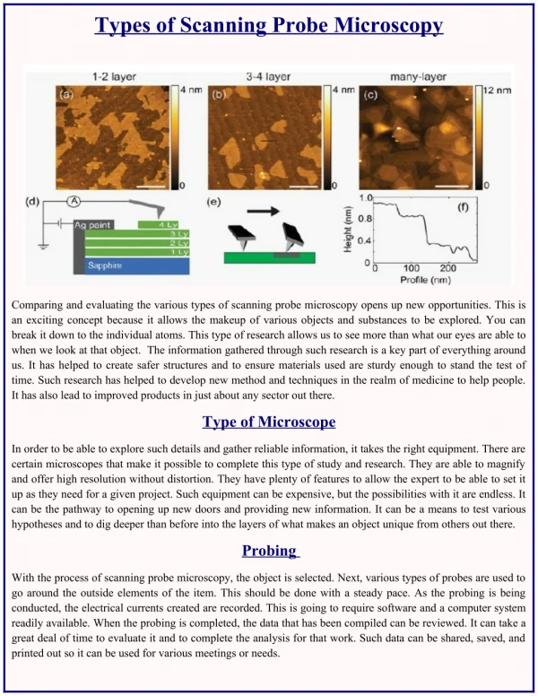
LECTURE 6 Scanning Probe Microscopy (AFM). Scanning probe microscopy (SPM) is a new branch of microscopy that forms images of surfaces using a physical probe that scans the specimen.

LECTURE 6 Scanning Probe Microscopy (AFM)
E N D
Presentation Transcript
LECTURE 6Scanning Probe Microscopy (AFM) UNIT IV LECTURE 6
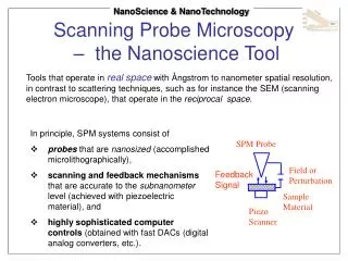
Scanning probe microscopy (SPM) is a new branch of microscopy that forms images of surfaces using a physical probe that scans the specimen. • An image of the surface is obtained by mechanically moving the probe in a raster scan of the specimen, line by line, and recording the probe-surface interaction as a function of position. • SPM was founded with the invention of the scanning tunneling microscope in 1981. UNIT IV LECTURE 6
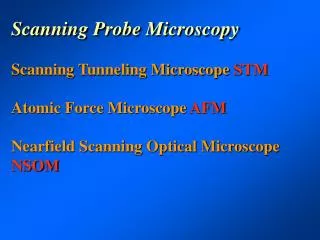
Some important types of scanning probe microscopy • AFM, atomic force microscopy • EFM, electrostatic force microscope • FMM, force modulation microscopy • MFM, magnetic force microscopy • STM, scanning tunneling microscopy • SVM, scanning voltage microscopy • SHPM, scanning Hall probe microscopy UNIT IV LECTURE 6
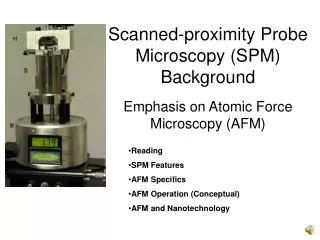
Atomic Force Microscope (AFM) • Introduction • The atomic force microscope (AFM) or scanning force microscope (SFM) was invented in1986 by Binnig, Quate and Gerber. • Similar to other scanning probe microscopes, the AFM raster scans a sharp probe over the surface of a sample and measures the changes in force between the probe tip and the sample. UNIT IV LECTURE 6
Working Concept • The physical parameter probed is a force resulting from different interactions. • The origin of these interactions can be ionic repulsion, van der Waals, capillary, electrostatic and magnetic forces, or elastic and plastic deformations. • Thus, an AFM image is generated by recording the force changes as the probe (or sample) is scanned in the x and y directions. • The sample is mounted on a piezoelectric scanner, which ensures three-dimensional positioning with high resolution. • The force is monitored by attaching the probe to a pliable cantilever, which acts as a spring, and measuring the bending or "deflection" of the cantilever. UNIT IV LECTURE 6
The larger the cantilever deflection, the higher the force that will be experienced by the probe. • Most instruments today use an optical method to measure the cantilever deflection with high resolution; a laser beam is focused on the free end of the cantilever, and the position of the reflected beam is detected by a position-sensitive detector (photodiode). • AFM cantilevers and probes are typically made of silicon or silicon nitride by micro fabrication techniques. UNIT IV LECTURE 6
Working concept of AFM UNIT IV LECTURE 6
Basic set-up of an AFM • In principle the AFM resembles a record player and a stylus profilometer. • The ability of an AFM to achieve near atomic scale resolution depends on the three essential components: • (1) a cantilever with a sharp tip, • (2) a scanner that controls the x-y-z position, and • (3) the feedback control and loop. UNIT IV LECTURE 6
Cantiliever with a sharp tip. The stiffness of the cantilever needs to be less the effective spring constant holding atoms together, which is on the order of 1 - 10 nN/nm. • The tip should have a radius of curvature less than 20-50 nm (smaller is better) a cone angle between 10-20 degrees. • 2. Scanner. The movement of the tip or sample in the x, y, and z-directions is controlled by a piezo-electric tube scanner, similar to those used in STM. • For typical AFM scanners, the maximum ranges for are 80 mm x 80 mm in the x-y plane and 5 mm for the z-direction. UNIT IV LECTURE 6
3. Feedback control.The forces that are exerted between the tip and the sample are measured by the amount of bending (or deflection) of the cantilever. • By calculating the difference signal in the photodiode quadrants, the amount of deflection can be correlated with a height . • Because the cantilever obeys Hooke's Law for small displacements, the interaction force between the tip and the sample can be determined. UNIT IV LECTURE 6
A summary of the different modes of operation is found below. UNIT IV LECTURE 6
Applications • The AFM is useful for obtaining three-dimensional topographic information of insulating and conducting structures with lateral resolution down to 1.5 nm and vertical resolution down to 0.05 nm. • These samples include clusters of atoms and molecules, individual macromolecules, and biologic al species (cells, DNA, proteins). • Unlike the preparation of samples for STM imaging, there is minimal sample preparation involved for AFM imaging. • Similar to STM operation, the AFM can operate in gas, ambient, and fluid environments and can measure physical properties including elasticity, adhesion, hardness, friction and chemical functionality. • A concise applications listing is given below. UNIT IV LECTURE 6
Metals: tooling studies, roughness measurements, corrosion studies... • Solid powder catalysts: aggregate structural determination, • Polymers: determination of morphology and surface properties, kinetic studies, aging phenomena, surface treatment modifications, adhesion force measurement and indentation, • Biological samples, biomaterials: macromolecules association and conformation studies, adsorption kinetic of molecules on polymer surfaces, • Nano- and microparticle structures, Langmuir-Blodgett. Film studies... UNIT IV LECTURE 6
Advantages • The AFM has several advantages over the scanning electron microscope (SEM). • Unlike the electron microscope which provides a two-dimensional projection or a two-dimensional image of a sample, the AFM provides a true three-dimensional surface profile. • Additionally, samples viewed by AFM do not require any special treatments (such as metal/carbon coatings) that would irreversibly change or damage the sample. UNIT IV LECTURE 6
While an electron microscope needs an expensive vacuum environment for proper operation, most AFM modes can work perfectly well in ambient air or even a liquid environment. • This makes it possible to study biological macromolecules and even living organisms. • In principle, AFM can provide higher resolution than SEM. It has been shown to give true atomic resolution in ultra-high vacuum (UHV). UNIT IV LECTURE 6
Disadvantages • A disadvantage of AFM compared with the scanning electron microscope (SEM) is the image size. • The SEM can image an area on the order of millimetres by millimetres with a depth of field on the order of millimetres. • The AFM can only image a maximum height on the order of micrometres and a maximum scanning area of around 150 by 150 micrometres. • Another inconvenience is that at high resolution, the quality of an image is limited by the radius of curvature of the probe tip, and an incorrect choice of tip for the required resolution can lead to image artifacts. UNIT IV LECTURE 6
Traditionally the AFM could not scan images as fast as an SEM, requiring several minutes for a typical scan, while an SEM is capable of scanning at near real-time (although at relatively low quality) after the chamber is evacuated. • AFM images can be affected by hysteresis of the piezoelectric material . UNIT IV LECTURE 6