Scanning Probe Microscopy Scanning Tunneling Microscope STM Atomic Force Microscope AFM
360 likes | 858 Vues
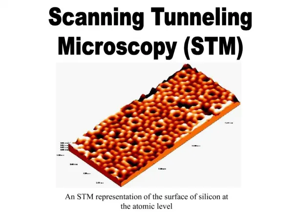
Scanning Probe Microscopy Scanning Tunneling Microscope STM Atomic Force Microscope AFM Nearfield Scanning Optical Microscope NSOM. HEINRICH ROHRER. GERD BINNIG. “IBM” spelled in Xenon atoms.

Scanning Probe Microscopy Scanning Tunneling Microscope STM Atomic Force Microscope AFM
E N D
Presentation Transcript
Scanning Probe Microscopy Scanning Tunneling Microscope STM Atomic Force Microscope AFM Nearfield Scanning Optical Microscope NSOM
HEINRICH ROHRER GERD BINNIG “IBM” spelled in Xenon atoms Shared* the 1986 Nobel prize in Physics for their invention of the scanning tunneling microscope
HEINRICH ROHRER GERD BINNIG “IBM” spelled in Xenon atoms Shared* the 1986 Nobel prize in Physics for their invention of the scanning tunneling microscope * Ernst Ruska was the other winner
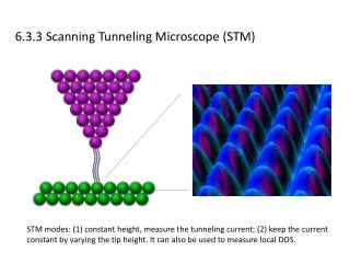
Electron Tunneling: In scanning tunnneling microscopy a small bias voltage V is applied so that due to the electric field the tunneling of electrons results in a tunneling current I. The height of the barrier can roughly be approximated by the average workfunction of sample and tip.
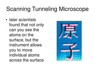
When the tip of the STM probe is sufficiently close to the surface of the specimen (~ 1nm) a tunneling current can become established
Ideally a STM probe tip is very pointed (1-2 atoms at the end) and has a relatively low work function. Etched tungsten crystals are ideal and are nearly identical to field emitters.
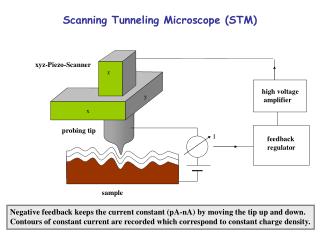
The tunneling current is exponentially proportional to the distance and thus via a feedback loop the tip can be maintained at a constant distance from the surface by maintaining a constant tunneling current.
If the tunneling current is kept constant the Z position of the tip must be moved up and down. If this movement is recorded then the topography of the specimen can be inferred.
Alternatively if the Z position of the tip is kept constant the tunneling current will change as it moves across the surface. If the changes in current are recorded the then the topography of the specimen can be inferred.
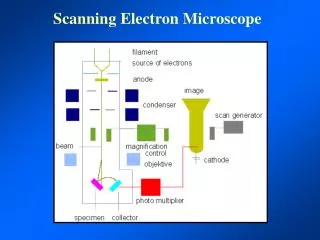
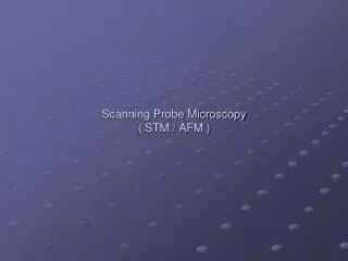
The probe is scanned over the surface in a raster pattern similar to that of a SEM or Confocal. Each coordinate (X,Y, & Z) is recorded by a computer.
The ability to precisely position the probe of an STM is made possible by an XYZ Piezo-Scanner which coupled to a feedback regulator keeps track of the tunneling current and precisely positions the tip accordingly.
Crystals which acquire a charge when compressed, twisted or distorted are said to be piezoelectric. Piezoelectric ceramic materials have found use in producing motions on the order of nanometers in the control of STMs and other devices.
The Piezoelectric Effect: Forces applied to a segment of material lead to the appearance of electrical charge on the surfaces of the segment. The specific distribution of electric charges in the unit cell of a crystal is the source of this phenomenon.
Iron corrals on Cu Positioning of atoms for a mass data storage system
~ ATOMIC FORCE MICROSCOPE ~ Feedback Loop Laser V Photodiode Piezo Crystal Mirror Tip Substrate ThermoMicroscopes Explorer AFM HOW DOES IT WORK? The atomic force microscope (AFM), uses a sharp tip attached to the end of a cantilever rasters across an area while a laser and photodiode are used to monitor the tip force on the surface. A feedback loop between the photodiode and the piezo crystal maintains a constant force during contact mode imaging and constant amplitude during intermittent contact mode imaging.
As with the STM the probe tip of an AFM must be very small but because there is no need to establish a tunneling current one can use a variety of materials, not just those with a low workfunction.
Similar to a phonograph needle the probe is actually in contact with the specimen and is physically moved up and down due to the repulsion of van der Waals forces
The AFM records the position of the probe by bouncing a laser off the back surface of the probe and recording how the light is deflected
By using a four quadrant detector the relative amount of laser light hitting each quadrant can be used to determine how the tip has been deflected as it moves over the surface of the specimen
AFM of Chromosome Since an AFM relies on contact rather than current many nonconductive materials can be examined AFM derived models of nuclear pore complex
Since the contact of the tip with the specimen can cause physical damage to the specimen many AFMs employ a “tapping” mode in which the probe vibrates up and down as the sample is moved.
~ ATOMIC FORCE MICROSCOPE ~ Imaging direction TIP Height Rc Width WHAT CAN WE LEARN? Topography Mechanical Properties Elasticity Friction AFM Image and manipulation of an Adenovirus. Binding
A recent development uses an AFM to “write” with biomolecules such as DNA sequences. This will allow for the creation of micro DNA chips which can be used a wide variety of applications
There are now a number of systems that combine an AFM with a conventional inverted microscope so that light and surface information can be collected from the same samples
Nearfield Scanning Optical Microscopy (NSOM) In NSOM a subwavelength (20 - 200 nm) aperture is placed in close proximity to the surface to be imaged (of the order of 10 nm). Light passing through the aperture remains collimated for a distance of the order of one aperture diameter. If the aperture is maintained in the near-field and scanned over a sample surface, an image can be reconstructed point by point with spatial resolution limited by the aperture diameter rather than the wavelength of light.
A key technological advance was the development of the tapered optical fiber probe by Betzig and Trautman et. al. in 1991. Tapered optical fiber tips are fabricated from single mode optical fiber using a commercially available micro pipette puller with a focused carbon dioxide laser as the heat source. The aperture is formed by coating the tapered fiber with a high reflectivity metal (Al or Ag) via standard thermal evaporation.
As with STM the probe is rastered by the movement of a Piezo-electric device
AFM vs. STM vs. NSOM In all three resolution is largely dependent on probe size and the ability to control scanning. STM requires a conductive specimen, AFM and NSOM do not and both of these can be used in air, vacuum, or in liquids. AFM physically contact the specimen but STM and NSOM do not.
A schematic of an atomic force microscope is shown in the diagram above. The sample is mounted on a piezo ceramic which can be moved extremely accurately in the x, y and z directions. The sample is then rastered in the x and y directions under a sharp tip. This tip is mounted at the free end of a cantilever (as shown) onto which a laser beam is focussed. The beam is reflected from the back of the cantilever to a set of four photosensitive diodes. These act to detect any deflection of the laser beam arising from the cantilever moving as the sample is rastered. A feedback loop then acts to move the piezo in the z direction taking the laser beam back to its original position. In this way the sample is scanned with a constant force and the resulting z piezo motion produce a How the AFM works. topographical map of the region scanned with a vertical resolution much smaller than 1A; in favorable cases. The AFM can be used in a variety of environments, in air,in UHV or under liquids.