Download
1 / 49
590 likes | 1.07k Vues
Closed-loop Control of DC Drives with Controlled Rectifier By Mr.M.Kaliamoorthy Department of Electrical & Electronics Engineering PSNA College of Engineering and Technology. Outline. Closed Loop Control of DC Drives Closed-loop Control with Controlled Rectifier – Two-quadrant

E N D
Closed-loop Control of DC Drives with Controlled Rectifier By Mr.M.Kaliamoorthy Department of Electrical & Electronics Engineering PSNA College of Engineering and Technology Solid State Drives
Outline • Closed Loop Control of DC Drives • Closed-loop Control with Controlled Rectifier – Two-quadrant • Transfer Functions of Subsystems • Design of Controllers • Closed-loop Control with Field Weakening – Two-quadrant • Closed-loop Control with Controlled Rectifier – Four-quadrant • References Solid State Drives
Closed Loop Control of DC Drives • Closed loop control is when the firing angle is varied automatically by a controller to achieve a reference speed or torque • This requires the use of sensors to feed back the actual motor speed and torque to be compared with the reference values Output signal Referencesignal Plant Controller + Sensor Solid State Drives
Closed Loop Control of DC Drives • Feedback loops may be provided to satisfy one or more of the following: • Protection • Enhancement of response – fast response with small overshoot • Improve steady-state accuracy • Variables to be controlled in drives: • Torque – achieved by controlling current • Speed • Position Solid State Drives
Closed Loop Control of DC Drives • Cascade control structure • Flexible – outer loops can be added/removed depending on control requirements. • Control variable of inner loop (eg: speed, torque) can be limited by limiting its reference value • Torque loop is fastest, speed loop – slower and position loop - slowest Solid State Drives
Closed Loop Control of DC Drives • Cascade control structure: • Inner Torque (Current) Control Loop: • Current control loop is used to control torque via armature current (ia) and maintains current within a safe limit • Accelerates and decelerates the drive at maximum permissible current and torque during transient operations Torque (Current) Control Loop Solid State Drives
Closed Loop Control of DC Drives • Cascade control structure • Speed Control Loop: • Ensures that the actual speed is always equal to reference speed * • Provides fast response to changes in *, TL and supply voltage (i.e. any transients are overcome within the shortest feasible time) without exceeding motor and converter capability Speed Control Loop Solid State Drives
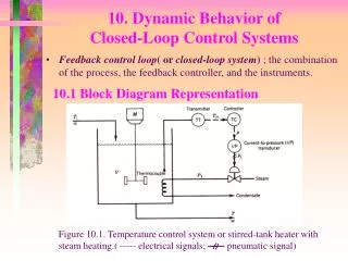
Closed Loop Control with Controlled Rectifiers – Two-quadrant Current Control Loop • Two-quadrant Three-phase Controlled Rectifier DC Motor Drives Speed Control Loop Solid State Drives
Closed Loop Control with Controlled Rectifiers – Two-quadrant • Actual motor speed m measured using the tachogenerator (Tach) is filtered to produce feedback signal mr • The reference speed r* is compared to mrto obtain a speed error signal • The speed (PI) controllerprocesses the speed error and produces the torque command Te* • Te* is limited by the limiter to keep within the safe current limits and the armature current command ia* is produced • ia* is compared to actual current ia to obtain a current error signal • The current (PI) controllerprocesses the error to alter the control signal vc • vc modifies the firing angle to be sent to the converter to obtained the motor armature voltage for the desired motor operation speed Solid State Drives
Closed Loop Control with Controlled Rectifiers – Two-quadrant • Design of speed and current controller (gain and time constants) is crucial in meeting the dynamic specifications of the drive system • Controller design procedure: • Obtain the transfer function of all drive subsystems • DC Motor & Load • Current feedback loop sensor • Speed feedback loop sensor • Design current (torque) control loop first • Then design the speed control loop Solid State Drives
Transfer Function of Subsystems – DC Motor and Load • Assume load is proportional to speed • DC motor has inner loop due to induced emf magnetic coupling, which is not physically seen • This creates complexity in current control loop design Solid State Drives
Transfer Function of Subsystems – DC Motor and Load • Need to split the DC motor transfer function between m and Va (1) • where (2) (3) • This is achieved through redrawing of the DC motor and load block diagram. Back Solid State Drives
Transfer Function of Subsystems – DC Motor and Load • In (2), - mechanical motor time constant: (4) - motor and load friction coefficient: (5) • In (3), (6) (7) Note: J = motor inertia, B1 = motor friction coefficient, BL = load friction coefficient Back Solid State Drives
Transfer Function of Subsystems – Three-phase Converter • Need to obtain linear relationship between control signal vc and delay angle (i.e. using ‘cosine wave crossing’ method) (8) where vc = control signal (output of current controller) Vcm = maximum value of the control voltage • Thus, dc output voltage of the three-phase converter (9) Solid State Drives
Transfer Function of Subsystems – Three-phase Converter • Gain of the converter (10) where V = rms line-to-line voltage of 3-phase supply • Converter also has a delay (11) where fs = supply voltage frequency • Hence, the converter transfer function (12) Back Solid State Drives
Transfer Function of Subsystems – Current and Speed Feedback • Current Feedback • Transfer function: • No filtering is required in most cases • If filtering is required, a low pass-filter can be included (time constant < 1ms). • Speed Feedback • Transfer function: (13) where K = gain, T = time constant • Most high performance systems use dc tacho generator and low-pass filter • Filter time constant < 10 ms Solid State Drives
Design of Controllers – Block Diagram of Motor Drive • Control loop design starts from inner (fastest) loop to outer(slowest) loop • Only have to solve for one controller at a time • Not all drive applications require speed control (outer loop) • Performance of outer loop depends on inner loop Current Control Loop Speed Control Loop Solid State Drives
Design of Controllers– Current Controller DC Motor & Load Controller Converter • PI type current controller: (14) • Open loop gain function: (15) • From the open loop gain, the system is of 4th order (due to 4 poles of system) Solid State Drives
Design of Controllers– Current Controller • If designing without computers, simplification is needed. • Simplification 1: Tm is in order of 1 second. Hence, (16) Hence, the open loop gain function becomes: i.e. system zero cancels the controller pole at origin. (17) Solid State Drives
Design of Controllers– Current Controller • Relationship between the denominator time constants in (17): • Simplification 2: Make controller time constant equal to T2 (18) Hence, the open loop gain function becomes: i.e. controller zero cancels one of the system poles. Solid State Drives
Design of Controllers– Current Controller • After simplification, the final open loop gain function: (19) where (20) • The system is now of 2nd order. • From the closed loop transfer function: , the closed loop characteristic equation is: or when expanded becomes: (21) Solid State Drives
Design of Controllers– Current Controller • Design the controller by comparing system characteristic equation (eq. 21) with the standard 2nd order system equation: • Hence, • So, for good dynamic performance =0.707 • Hence equating the damping ratio to 0.707 in (23) we get Solid State Drives
Which leads to An approximation K >> 1 & Equating above expression with (20) we get the gain of current controller Back
Design of Controllers– Current loop 1st order approximation • To design the speed loop, the 2nd order model of current loop must be replaced with an approximate 1st order model • Why? • To reduce the order of the overall speed loop gain function 2nd order current loop model Solid State Drives
Design of Controllers– Current loop 1st order approximation • Approximated by adding Tr to T1 • Hence, current model transfer function is given by: (24) 1st order approximation of current loop Full derivation available here. Solid State Drives
Design of Controllers– Current Controller • After simplification, the final open loop gain function: Where Since and since Therefore Solid State Drives
Design of Controllers– Current loop 1st order approximation where (26) (27) (28) • 1st order approximation of current loop used in speed loop design. • If more accurate speed controller design is required, values of Kiand Tishould be obtained experimentally. Solid State Drives
Design of Controllers– Speed Controller DC Motor & Load • PI type speed controller: (29) • Assume there is unity speed feedback: (30) 1st order approximation of current loop Solid State Drives
Design of Controllers– Speed Controller DC Motor & Load • Open loop gain function: (31) • From the loop gain, the system is of 3rd order. • If designing without computers, simplification is needed. 1st order approximation of current loop 1 Solid State Drives
Design of Controllers– Speed Controller • Relationship between the denominator time constants in (31): (32) • Hence, design the speed controller such that: (33) The open loop gain function becomes: i.e. controller zero cancels one of the system poles. Solid State Drives
Design of Controllers– Speed Controller • After simplification, loop gain function: (34) where (35) • The controller is now of 2nd order. • From the closed loop transfer function: , the closed loop characteristic equation is: or when expanded becomes: (36) Solid State Drives
Design of Controllers– Speed Controller • Design the controller by comparing system characteristic equation with the standard equation: • Hence: (37) (38) • So, for a given value of : • use (37) to calculate n • Then use (38) to calculate the controller gain KS Solid State Drives
Closed Loop Control with Field Weakening – Two-quadrant • Motor operation above base speed requires field weakening • Field weakening obtained by varying field winding voltage usingcontrolled rectifier in: • single-phase or • three-phase • Field current has no ripple – due to large Lf • Converter time lag negligible compared to field time constant • Consists of two additional control loops on field circuit: • Field current control loop (inner) • Induced emf control loop (outer) Solid State Drives
Closed Loop Control with Field Weakening – Two-quadrant Field weakening Solid State Drives
Closed Loop Control with Field Weakening – Two-quadrant Field weakening Field current controller (PI-type) Estimated machine -induced emf Induced emf controller (PI-type with limiter) Field current reference Induced emf reference Solid State Drives
Closed Loop Control with Field Weakening – Two-quadrant • The estimated machine-induced emfis obtained from: (the estimated emf is machine-parameter sensitive and must be adaptive) • The reference induced emfe* is compared to e to obtain the induced emf error signal (for speed above base speed, e* kept constant at rated emf value so that 1/) • The induced emf (PI) controllerprocesses the error and produces the field current reference if* • if* is limited by the limiter to keep within the safe field current limits • if* is compared to actual field current if to obtain a current error signal • The field current (PI) controllerprocesses the error to alter the control signal vcf(similar to armature current iacontrol loop) • vcfmodifies the firing angle fto be sent to the converter to obtained the motor field voltage for the desired motor field flux Solid State Drives
Closed Loop Control with Controlled Rectifiers – Four-quadrant • Four-quadrant Three-phase Controlled Rectifier DC Motor Drives Solid State Drives
Closed Loop Control with Controlled Rectifiers – Four-quadrant • Control very similar to the two-quadrant dc motor drive. • Each converter must be energized depending on quadrant of operation: • Converter 1 – for forward direction / rotation • Converter 2 – for reverse direction / rotation • Changeover between Converters 1 & 2 handled by monitoring • Speed • Current-command • Zero-crossing current signals • ‘Selector’ block determines which converter has to operate by assigning pulse-control signals • Speed and current loops shared by both converters • Converters switched only when current in outgoing converter is zero (i.e. does not allow circulating current. One converter is on at a time.) Inputs to ‘Selector’ block Solid State Drives
References • Krishnan, R., Electric Motor Drives: Modeling, Analysis and Control, Prentice-Hall, New Jersey, 2001. • Rashid, M.H, Power Electronics: Circuit, Devices and Applictions, 3rd ed., Pearson, New-Jersey, 2004. • Nik Idris, N. R., Short Course Notes on Electrical Drives, UNITEN/UTM, 2008. Solid State Drives
DC Motor and Load Transfer Function - Decoupling of Induced EMF Loop • Step 1: • Step 2: Solid State Drives
DC Motor and Load Transfer Function - Decoupling of Induced EMF Loop • Step 3: • Step 4: Back Solid State Drives
3 4 2 0 Vcm vc Cosine-wave Crossing Control for Controlled Rectifiers Vm Input voltageto rectifier Cosine wave compared with control voltage vc Cosine voltage Vcmcos() = vc Results of comparison trigger SCRs Output voltageof rectifier Back Solid State Drives
Design of Controllers– Current loop 1st order approximation Back Solid State Drives
Go to Go to