The Network Layer
The Network Layer. Chapter 5. Network Layer Task. getting packets from the source all the way to the destination may require many hops through intermediate routers. This contrasts with the data link layer, which just moves frames from one end of a wire to another.

The Network Layer
E N D
Presentation Transcript
The Network Layer Chapter 5
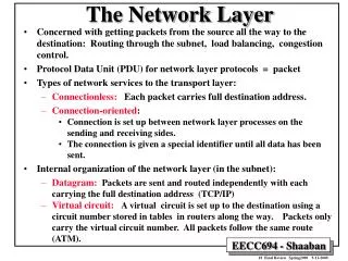
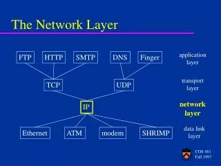
Network Layer Task • getting packets from the source all the way to the destination • may require many hops through intermediate routers. • This contrasts with the data link layer, which just moves frames from one end of a wire to another. • it must know about the topology of the communication subnet ( the set of all routers) and choose appropriate paths through it. • It must take care to choose routers to avoid overloading some of the lines and routers while leaving others idle. • When source and destination are in different networks, it has to deal with the differences.
Services to transport layer • Goals: • The services should be independent of the router technology • The transport layer should be shielded from the number, type and topology of the subnets present. • The network addresses made available to the transport layer should use a uniform numbering plan across LAN’s and WAN’s • The Internet community argues that a subnet is inherently unreliable, the hosts should do error control and flow control. The service should thus be connectionless, but as reliable as possible, and most of the complexity is placed on the hosts. • The telephone companies argue that the subnet should provide a reliable, connection-oriented service, placing the complexity in their subnets.
Implementation of Connection-Oriented Service A route from source to destination is chosen as part of the connection setup. Such a route is called a virtual circuit (VC). Each router along the path puts an entry in a table, linking a VC to an outgoing line.
Flooding A simple static algorithm is flooding, in which every incoming packet is sent out on every outgoing line except the one it arrived on. It generates a vast number of duplicate packets, an infinite number unless some measures are taken to damp the process. E.g. a hop counter in the header of each packet, which is decremented at each hop, and the packet is discarded when the counter reaches 0. In selective flooding the packets are only sent out on those lines that are going approximately in the right direction. Flooding might be usable in military applications, large numbers of routers may be blown to pieces at any instant, as it is very robust. Also during initialization of routers.
Shortest Path Routing • Subnet as an undirected graph • node: a router • arc: a communication link • labeled with a length. Dijkstra's (or another) algorithm is used to compute the path with the shortest length between any two nodes. In general the labels on the arcs can be computed as a function of distance, bandwidth, average traffic, communication costs, mean queue length, measured delay, etc.
Distance Vector Routing A routing table in each router contains for each router the preferred outgoing line for that router and an estimate for the “cost” to that destination. The cost metric might be number of hops, queue length, time delay, etc. Time delay is measured by periodically sending ECHO packets. Once every T msec each router sends to its neighbors a list of estimated “costs” to each destination.
Link State Routing Distance vector routing reacts slowly on bad news, e.g. break down of a link (count to infinity problem). The core of the problem is that when X tells Y that it has a path somewhere, Y has no way of knowing whether it itself is on the path. Link State Routing: each router sends costs to neighbors to all other routers. Each router must: • Discover its neighbors, learn their network address. • Measure the delay or cost to each of its neighbors. • Construct a packet telling all it has just learned. • Send this packet to all other routers. • Compute the shortest path to every other router.
Link State Packets The trickiest part is distributing the link state packages reliably, to assure that each router has basically the same view of the subnet. A 32 bit sequence number (sufficient for 137 years, if it is updated every second) is used. An age field is decremented every second and at every send and the packet is discarded if the age reaches 0. All link state packets are acknowledged.
Congestion When too many packets are present, buffers get full, packets are discarded, more retransmissions and less packets delivered. Congestion thus tends to feed upon itself and become worse, leading to collapse of the system. The reason congestion and flow control are often confused is that some congestion control algorithm operate by sending messages back to various sources, telling them to "slow down". Thus a host can get a "slow down" message either because the receiver on the direct link cannot handle the load or because the network cannot handle it.
Jitter Control For applications such as audio and video streaming, it does not matter much if the packets take 20 or 30 msec to be delivered, as long as the transit time is constant. The jitter should be small. In some applications, like video on demand, jitter can be compensated for by buffering at the receiver. For others, like Internet telephony or videoconferencing, the delay inherent in buffering is not acceptable.
Quality of Service • Constant bit rate (e.g. telephony), attempts to simulate a wire, providing uniform bandwidth and delay. • Variable bit rate (e.g. compressed videoconferencing), images must arrive in time independent on how much they could be compressed. • Non-real-time variable bit rate (e.g. watching a movie over internet), a lot of buffering at the receiver is allowed. • Available bit rate (e.g. file transfer), not sensitive to jitter or delay. • Not present in original Internet, becomes more and more important. • More or less provided by “sufficient bandwidth”
Fragmentation Transparent and non-transparent fragmentation.
The IPv4 Protocol The IHL field tells how long the header is, in 32 bit words. The Type of Service field contains a 3 bit Precedence field, used for the priority from 0 (normal) to 7 (network control packet), and 3 flags Delay, Throughput and Reliability, to specify what is most important for the packet. In practice, current routers mostly ignore the TOS field. The situation is changing.
Some options for IPv4 The Time to Live field is a counter to limit packet lifetimes, it must be decremented at each hop. The packet is discarded when TOL hits 0. The Protocol field tells the receiving host which transport process (TCP, UDP or other) the packet should be given to. The Header checksum verifies the header only, useful for detecting errors by bad memory bytes or corrupted software inside a router. It must be recomputed at each hop, because the TTL changes.
IP Addresses The class A, B resp. C formats allow for 126, 16382 resp. 2 million networks with 16 million, 64K resp. 254 hosts. Network addresses were given to organizations, leading to many unused host numbers.
Special IP Addresses IP addresses of the form 10.x.y.z (and other one) are intended for use within a LAN (company or home nowadays). They are not intended to go on the public internet.
CIDR – Classless InterDomain Routing Class A and B networks were given out, Class C were too small. A basic idea is to allocate the remaining class C networks (more than 2 million, and later A and B) in variable sized blocks of 254 addresses, a site needing 8000 addresses then gets 32 contiguous class C networks. The world was divided up into 4 zones to easy hierarchical routing. A site outside Europe, that gets a packet destinated for 194... or 195... can just send it to its standard European gateway.
NAT – Network Address Translation Dirty trick! NAT makes the IP network in fact connection-oriented as it maintains information on each connection passing through it. A crash of the NAT box terminates every TCP connection. Some protocols send IP numbers (and port numbers) in data, to be used by the other side. They have been adapted or other ways are used.
Internet Control Message Protocol When something unexpected occurs in a router or host, this event is reported by ICMP. The most important messages are in the table. It is also used by routers to test the internet or to obtain information to be use in routing decisions. Each ICMP message is encapsulated in an IP packet.
ARP– The Address Resolution Protocol IP addresses must be linked to data link layer addresses, like Ethernet addresses or other types. With ARP the host broadcast a frame asking who owns a certain IP address, like E1 asking for 192.31.65.5. Host E2 alone will answer with a broadcast frame telling its IP and ethernet number. Entries in the ARP cache time out to allow for hardware changes.
Dynamic Host Configuration Protocol If a computer boots ups, what is it IP address? It could be a fixed number, which is in the computer. But this requires administrative procedures, which cost time and are error prone. DHCP (Dynamic Host Configuration Protocol) assigns IP addresses dynamically. Older protocols for this are RARP and BOOTP.
IPv6 The major goals of the new IPv6 protocol were: • Support billions of hosts, even with inefficient address space allocation • Reduce the size of the routing tables • Simplify the protocol, to allow routers to process packets faster • Provide better security (authentication and privacy) • Pay more attention to type of service, particularly for real time data • Aid multicasting by allowing scopes to be specified • Make it possible for a host to roam without changing its address • Allow the protocol to evolve in the future • Permit the old and the new protocols to coexist for years
The Main IPv6 Header Traffic class, is used to distinguish between packets whose sources can be flow controlled, values between 0 and 7, or not, values between 8 and 15. The flow label is also still experimental but will be used to allow a source and destination to set up a pseudo-connection with particular properties and requirements.
Extension Headers Extension header Description Hop-by-hop options Miscellaneous information for routersSupport for datagrams larger than 64K (jumbograms) Routing Full or partial route to follow Fragmentation Management of datagram fragmentsSimilar to IPv4, but only the sending host can fragment a packet Authentication Verification of the sender's identity Encrypted payload Information about the encryption Destination options Additional information for the destination The use of jumbograms is important for supercomputer applications that must transfer gigabytes efficiently across the Internet.The routing header list up to 24 routers that must be visited on the way to the destination. Both strict (the full path is supplied) and loose (only selected routers are supplied) are available, and they can be combined.
Addresses Prefix Usage Fraction 0000 0000 Reserved, including IPv4 1/256 0000 001 OSI NSAP addresses 1/128 0000 010 Novell IPX addresses 1/128 010 Provider-based addresses 1/8 100 Geographic-based addresses 1/8 1111 1110 10 Link local use addresses 1/1024 1111 1110 11 Site local use addresses 1/1024 1111 1111 Multicast 1/256 other unassigned 371/512 In addition to multicast, also anycast is supported. The destination is a group of addresses, but it is tried to deliver the packet to just 1 of them, usually the nearest one. This can be used for example to contact a group of cooperating file servers. The 16 byte addresses are written as 8 groups of 4 hexadecimal digits with colons between the groups, leading 0's can be left out and 1 or more groups of 16 0's can be replaced by a pair of colons.: 8000::123:4567:89AB:CDEF.