Download

1 / 6
90 likes | 227 Vues
Register-Transfer Level Components in Verilog. CS 153, Spring 2007 Ian G. Harris Department of Computer Science University of California Irvine. X. Y. ‘1’. ‘0’. >. Z. Next Assignment: Div/Mod, Structurally. Need to reimplement the Div/Mod structurally , not behaviorally

E N D
Register-Transfer Level Components in Verilog CS 153, Spring 2007 Ian G. Harris Department of Computer Science University of California Irvine
X Y ‘1’ ‘0’ > Z Next Assignment: Div/Mod, Structurally • Need to reimplement the Div/Mod structurally, not behaviorally • Build it using RTL (datapath) components • Need to determine how to implement behavioral operations structurally • Some tips: • Fixed length loops can be implemented with down counters and zero detectors • Left/right shift can be implemented using shift registers • Assignments within conditionals can be implemented using multiplexers to drive registers if (x > y) z = 1; else z = 0;
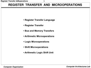
RTL Components • Built from gates and flip-flops • Operate on words rather than bits • Some are combinational, some are sequential • Data inputs vs. control inputs • Data outputs vs. status outputs Example: 8 bit ALU Inputs - in1 [7:0], in2[7:0], op[3:0] Outputs - out[7:0], cout
RTL Component Design • Define your RTL components behaviorally, not structurally • Combine RTL components structurally to create a larger design Example: 4 to 1 Multiplexer module mux4to1 (W, S, f); input [0:3] W, [1:0] S; output f; reg f; always @(W or S) case (S) 0: f= W[0]; 1: f= W[1]; 2: f= W[2]; 3: f= W[3]; endcase endmodule
Sequential Components module reg8 (D, Clock, Resetn, Q); input [7:0] D, Clock, Resetn; output [7:0] Q; reg [7:0] Q; always @(negedge Resetn or posedge Clock) if (!Resetn) Q <= 0; else Q <= D; endmodule • Reset is negatively asserted • You can add a clear or a shift function as needed
Components needed for a Div/Mod Register, 8 bit, needs a load signal Shift register, 8 or 16 bit, needs a load signal Subtractor, 8 bit Comparator Multiplexer, 8 bit, 2 way Counter - to stop after 8 iterations Comparator (or zero detector) - to detect last iteration • Notice that Div/Mod is sequential • Your testbench will need to generate a clock