Register-Transfer Level (RTL) Design
Register-Transfer Level (RTL) Design. Recall Chapter 2: Combinational Logic Design First step: Capture behavior (using equation or truth table) Remaining steps: Convert to circuit Chapter 3: Sequential Logic Design First step: Capture behavior (using FSM) Remaining steps: Convert to circuit

Register-Transfer Level (RTL) Design
E N D
Presentation Transcript
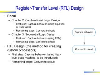
Register-Transfer Level (RTL) Design • Recall • Chapter 2: Combinational Logic Design • First step: Capture behavior (using equation or truth table) • Remaining steps: Convert to circuit • Chapter 3: Sequential Logic Design • First step: Capture behavior (using FSM) • Remaining steps: Convert to circuit • RTL Design (the method for creating custom processors) • First step: Capture behavior (using high-level state machine, to be introduced) • Remaining steps: Convert to circuit Capture behavior Convert to circuit
T (in seconds) laser D Object of interest sensor 2D = T sec * 3*108 m/sec Step 1: Laser-Based Distance Measurer • Example of how to create a high-level state machine to describe desired processor behavior • Laser-based distance measurement – pulse laser, measure time T to sense reflection • Laser light travels at speed of light, 3*108 m/sec • Distance is thus D = T sec * 3*108 m/sec / 2
B L from button to laser Laser-based distance 16 D S measurer to display from sensor Step 1: Laser-Based Distance Measurer • Inputs/outputs • B: bit input, from button to begin measurement • L: bit output, activates laser • S: bit input, senses laser reflection • D: 16-bit output, displays computed distance T (in seconds) laser sensor
B L from button to laser Laser- based distance 16 D S measurer to display from sensor S0 ? L = 0 (laser off) D = 0 (distance = 0) Step 1: Laser-Based Distance Measurer • Step 1: Create high-level state machine • Begin by declaring inputs and outputs • Create initial state, name it S0 • Initialize laser to off (L=0) • Initialize displayed distance to 0 (D=0) Inputs: B , S (1 bit each) Outputs: L (bit), D (16 bits) a
B L from button to laser Laser- based distance B’ (button not pressed) 16 D S measurer to display from sensor ? S1 B (button pressed) Step 1: Laser-Based Distance Measurer Inputs: B, S (1 bit each) • Add another state, call S1, that waits for a button press • B’ – stay in S1, keep waiting • B – go to a new state S2 Outputs: L (bit), D (16 bits) a S0 S0 L = 0 D = 0 Q: What should S2 do? A: Turn on the laser a
B L from button to laser Laser- based distance 16 D S measurer to display from sensor S3 L = 0 (laser off) Step 1: Laser-Based Distance Measurer Inputs: B, S (1 bit each) • Add a state S2 that turns on the laser (L=1) • Then turn off laser (L=0) in a state S3 Outputs: L (bit), D (16 bits) B’ S0 S1 S2 B a L = 0 L = 1 D = 0 (laser on) Q: What do next? A: Start timer, wait to sense reflection a
B L f r om but t on S’ (no reflection) t o laser Lase r -based distan c e 16 D S measu r er S (reflection) t o displ a y f r om sensor ? Dctr = 0 (reset cycle Dctr = Dctr + 1 count) (count cycles) Step 1: Laser-Based Distance Measurer Inputs: B, S (1 bit each) Outputs: L (bit), D (16 bits) • Stay in S3 until sense reflection (S) • To measure time, count cycles for which we are in S3 • To count, declare local register Dctr • Increment Dctr each cycle in S3 • Initialize Dctr to 0 in S1. S2 would have been O.K. too Local Registers: Dctr (16 bits) B’ S0 S1 S2 S3 B L = 0 L = 1 L = 0 a D = 0
B L f r om but t on t o laser Lase r -based distan c e 16 D S measu r er t o displ a y f r om sensor S4 D = Dctr / 2 (calculate D) Step 1: Laser-Based Distance Measurer • Once reflection detected (S), go to new state S4 • Calculate distance • Assuming clock frequency is 3x10⁸, Dctr holds number of meters, so D=Dctr/2 • After S4, go back to S1 to wait for button again Inputs: B, S (1 bit each) Outputs: L (bit), D (16 bits) Local Registers: Dctr (16 bits) S’ B’ a S0 S1 S2 S3 B S L = 0 Dctr = 0 L = 1 L=0 D = 0 Dctr = Dctr + 1
Step 2: Create a Datapath • Datapath must • Implement data storage • Implement data computations • Look at high-level state machine, do three substeps • (a) Make data inputs/outputs be datapath inputs/outputs • (b) Instantiate declared registers into the datapath (also instantiate a register for each data output) • (c) Examine every state and transition, and instantiate datapath components and connections to implement any data computations Instantiate: to introduce a new component into a design.
Local Registers: Dctr (16 bits) ‘ ‘ B S S4 S0 S1 S2 S3 B S L = 0 Dctr = 0 L = 1 L=0 D = Dctr / 2 D = 0 Dctr = Dctr + 1 (calculate D) D r eg_clr D r eg_ld clear clear I D c tr_clr D c t r : 16-bit D r eg: 16-bit c ou n t D c tr_c n t load u p - c ou n t er r e g is t er Q Q 16 D Step 2: Laser-Based Distance Measurer (a) Make data inputs/outputs be datapath inputs/outputs (b) Instantiate declared registers into the datapath (also instantiate a register for each data output) (c) Examine every state and transition, and instantiate datapath components and connections to implement any data computations Inputs: B, S (1 bit each) Outputs: L (bit), D (16 bits) a D a tap a th
Local Registers: Dctr (16 bits) ‘ ‘ B S S4 S0 S1 S2 S3 B S L = 0 Dctr = 0 L = 1 L=0 D = Dctr / 2 D = 0 Dctr = Dctr + 1 (calculate D) >>1 16 16 Step 2: Laser-Based Distance Measurer (c) (continued) Examine every state and transition, and instantiate datapath components and connections to implement any data computations Inputs: B, S (1 bit each) Outputs: L (bit), D (16 bits) a D a tap a th D r eg_clr D r eg_ld clear clear I D c tr_clr D c t r : 16-bit D r eg: 16-bit c ou n t D c tr_c n t load u p - c ou n t er r e g is t er Q Q 16 D
L B to laser from button Controller from sensor S Dreg_clr Dreg_ld Dctr_clr Datapath Dctr_cnt D to display >>1 16 300 M H z Clock 16 Datapath Dreg_clr Dreg_ld 16 Dctr_clr clear clear I Dctr: 16-bit Dreg: 16-bit Dctr_cnt count load up-counter register Q Q 16 D Step 3: Connecting the Datapath to a Controller • Laser-based distance measurer example • Easy – just connect all control signals between controller and datapath
Inputs: B, S (1 bit each) Outputs: L (bit), D (16 bits) L B Local Registers: Dctr (16 bits) t o laser f r om but t on C o n t r oller r om sensor f S D r eg_clr B’ S’ D r eg_ld D c tr_clr D a tap a th S0 S1 S2 S3 S4 B S D c tr_c n t L = 0 Dctr = 0 L = 1 L=0 D = Dctr / 2 D D = 0 Dctr = Dctr + 1 (calculate D) t o displ a y 16 300 M H z Clock Inputs: B, S Outputs: L, Dreg_clr, Dreg_ld, Dctr_clr, Dctr_cnt B’ S’ B S S0 S1 S2 S3 S4 L = 0 L = 0 L = 1 L = 0 L = 0 Step 4: Deriving the Controller’s FSM • FSM has same structure as high-level state machine • Inputs/outputs all bits now • Replace data operations by bit operations using datapath a Dreg_clr = 1 Dreg_ld = 0 Dctr_clr = 0 Dctr_cnt = 0 (laser off) (clear D reg) Dreg_clr = 0 Dreg_ld = 0 Dctr_clr = 1 Dctr_cnt = 0 (clear count) Dreg_clr = 0 Dreg_ld = 0 Dctr_clr = 0 Dctr_cnt = 0 (laser on) Dreg_clr = 0 Dreg_ld = 0 Dctr_clr = 0 Dctr_cnt = 1 (laser off) (count up) Dreg_clr = 0 Dreg_ld = 1 Dctr_clr = 0 Dctr_cnt = 0 (load D reg with Dctr/2) (stop counting)
Inputs: B, S Outputs: L, Dreg_clr, Dreg_ld, Dctr_clr, Dctr_cnt B’ S’ B’ S’ B S S0 S1 S2 S3 S4 B S S0 S1 S2 S3 S4 L = 0 L = 0 L = 1 L = 0 L = 0 Dreg_clr = 1 Dreg_ld = 0 Dctr_clr = 0 Dctr_cnt = 0 (laser off) (clear D reg) Dreg_clr = 0 Dreg_ld = 0 Dctr_clr = 1 Dctr_cnt = 0 (clear count) Dreg_clr = 0 Dreg_ld = 0 Dctr_clr = 0 Dctr_cnt = 0 (laser on) Dreg_clr = 0 Dreg_ld = 0 Dctr_clr = 0 Dctr_cnt = 1 (laser off) (count up) Dreg_clr = 0 Dreg_ld = 1 Dctr_clr = 0 Dctr_cnt = 0 (load D reg with Dctr/2) (stop counting) L = 0 Dctr_clr = 1 (clear count) L = 1 L = 0 Dreg_ld = 1 Dctr_cnt = 0 (load D reg with Dctr/2) (stop counting) Dreg_clr = 1 (laser off) (clear D reg) (laser on) Dctr_cnt = 1 (laser off) (count up) Step 4: Deriving the Controller’s FSM • Using shorthand of outputs not assigned implicitly assigned 0 a
Datapath L B to laser from button from sensor S Dreg_clr Controller Dreg_clr Dreg_ld Datapath Dctr_clr clear clear I Dctr: 16-bit Dreg: 16-bit Dctr_cnt count load up-counter D register to display Q Q 300 MHz Clock 16 16 D Inputs: B, S Outputs: L, Dreg_clr, Dreg_ld, Dctr_clr, Dctr_cnt >>1 16 B’ S’ B S S0 S1 S2 S3 S4 16 L = 0 Dctr_clr = 1 (clear count) L = 1 L = 0 Dreg_ld = 1 Dctr_cnt = 0 (load D reg with Dctr/2) (stop counting) Dreg_clr = 1 (laser off) (clear D reg) (laser on) Dctr_cnt = 1 (laser off) (count up) Step 4 • Implement FSM as state register and logic (Ch3) to complete the design Dreg_ld Dctr_clr Dctr_cnt
Only difference: ball moving Frame 1 Frame 2 Frame 1 Frame 2 Digitized Digitized Digitized Difference of frame 1 frame 2 frame 1 2 from 1 1 Mbyte 1 Mbyte 1 Mbyte 0.01 Mbyte ( a ) ( b ) Just send difference RTL Example: Video Compression – Sum of Absolute Differences • Video is a series of frames (e.g., 30 per second) • Most frames similar to previous frame • Compression idea: just send difference from previous frame a
RTL Example: Video Compression – Sum of Absolute Differences compare • Need to quickly determine whether two frames are similar enough to just send difference for second frame • Compare corresponding 16x16 “blocks” • Treat 16x16 block as 256-byte array • Compute the absolute value of the difference of each array item • Sum those differences – if above a threshold, send complete frame for second frame; if below, can use difference method (using another technique, not described) Assume each pixel is represented as 1 byte (actually, a color picture might have 3 bytes per pixel, for intensity of red, green, and blue components of pixel) Frame 1 Frame 2
RTL Example: Video Compression – Sum of Absolute Differences • Want fast sum-of-absolute-differences (SAD) component • When go=1, sums the differences of element pairs in arrays A and B, outputs that sum SAD 256-byte array A integer sad B 256-byte array go !(i<256)
SAD A !go S0 sad B go go sum = 0 S1 i = 0 (i<256)’ S2 i<256 sum=sum+abs(A[i]-B[i]) S3 i=i+1 sad_ r eg = sum S4 RTL Example: Video Compression – Sum of Absolute Differences • S0: wait for go • S1: initialize sum and index • S2: check if done (i>=256) • S3: add difference to sum, increment index • S4: done, write to output sad_reg Inputs: A, B (256 byte memory); go (bit) Outputs: sad (32 bits) Local registers: sum, sad_reg (32 bits); i (9 bits) a !(i<256)
RTL Example: Video Compression – Sum of Absolute Differences • Step 2: Create datapath AB_addr A_data B_data Inputs: A, B (256 byte memory); go (bit) Outputs: sad (32 bits) Local registers: sum, sad_reg (32 bits); i (9 bits) i_lt_256 <256 8 8 9 i_inc !go S0 – i go i_clr sum = 0 8 S1 i = 0 sum_ld 32 (i<256)’ abs sum S2 sum_clr 8 i<256 !(i<256) 32 32 sum=sum+abs(A[i]-B[i]) sad_reg_ld S3 i=i+1 + sad_reg !(i<256) (i_lt_256) sad_ reg=sum S4 32 Datapath sad
sum_clr=1 i_clr=1 i_lt_256 sum_ld=1; AB_rd=1 i_inc=1 sad_reg_ld=1 RTL Example: Video Compression – Sum of Absolute Differences • Step 3: Connect to controller • Step 4: Replace high-level state machine by FSM AB_addr A_data B_data go AB_ r d i_lt_256 <256 8 8 go’ S0 9 i_inc go – i sum=0 S1 i_clr i=0 8 sum_ld S2 ? 32 abs sum i<256 sum_clr sum=sum+abs(A[i]-B[i]) S3 8 32 32 !(i<256) i=i+1 sad_reg_ld + S4 sad_reg=sum sad_reg a !(i<256) (i_lt_256) !(i<256) (i_lt_256) 32 Controller sad
RTL Example: Video Compression – Sum of Absolute Differences • Comparing software and custom circuit SAD • Circuit: Two states (S2 & S3) for each i, 256 i’s 512 clock cycles • Software: Loop (for i = 1 to 256), but for each i, must move memory to local registers, subtract, compute absolute value, add to sum, increment i – say about 6 cycles per array item 256*6 = 1536 cycles • Circuit is about 3 times (300%) faster (i<256)’ S2 i<256 sum=sum+abs(A[i]-B[i]) S3 i=i+1 !(i<256) !(i<256) (i_lt_256)
Control vs. Data Dominated RTL Design • Designs often categorized as control-dominated or data-dominated • Control-dominated design – Controller contains most of the complexity • Data-dominated design – Datapath contains most of the complexity • General, descriptive terms – no hard rule that separates the two types of designs • Laser-based distance measurer – control dominated • SAD circuit – mix of control and data • Now let’s do a data dominated design
Data Dominated RTL Design Example: FIR Filter • Filter concept • Suppose X is data from a temperature sensor, and particular input sequence is 180, 180, 181, 240, 180, 181 (one per clock cycle) • That 240 is probably wrong! • Could be electrical noise • Filter should remove such noise in its output Y • Simple filter: Output average of last N values • Small N: less filtering • Large N: more filtering, but less sharp output Y X 12 12 digital filter clk
Data Dominated RTL Design Example: FIR Filter • FIR filter • “Finite Impulse Response” • Simply a configurable weighted sum of past input values • y(t) = c0*x(t) + c1*x(t-1) + c2*x(t-2) • Above known as “3 tap” • Tens of taps more common • Very general filter – User sets the constants (c0, c1, c2) to define specific filter • RTL design • Step 1: Create high-level state machine • But there really is none! Data dominated indeed. • Go straight to step 2 Y X 12 12 digital filter clk y(t) = c0*x(t) + c1*x(t-1) + c2*x(t-2)
Y X 12 12 digital filter clk 180 240 180 181 181 Data Dominated RTL Design Example: FIR Filter • Step 2: Create datapath • Begin by creating chain of xt registers to hold past values of X y(t) = c0*x(t) + c1*x(t-1) + c2*x(t-2) Suppose sequence is: 180, 181, 240 180 a
Y X 12 12 digital filter clk c0 c1 c2 * * * Data Dominated RTL Design Example: FIR Filter • Step 2: Create datapath (cont.) • Instantiate registers for c0, c1, c2 • Instantiate multipliers to compute c*x values y(t) = c0*x(t) + c1*x(t-1) + c2*x(t-2) 3-tap FIR filter x(t) x( t -1) x( t -2) x t0 x t1 x t2 X a clk Y
Y X 12 12 digital filter clk + + Data Dominated RTL Design Example: FIR Filter • Step 2: Create datapath (cont.) • Instantiate adders y(t) = c0*x(t) + c1*x(t-1) + c2*x(t-2) 3-tap FIR filter x(t) x( t -1) x( t -2) c0 c1 c2 x t0 x t1 x t2 X clk a * * * Y
Y X 12 12 digital filter clk Data Dominated RTL Design Example: FIR Filter • Step 2: Create datapath (cont.) • Add circuitry to allow loading of particular c register y(t) = c0*x(t) + c1*x(t-1) + c2*x(t-2) CL 3-tap FIR filter e 3 Ca1 2x4 2 1 Ca0 0 C x(t) x(t-1) x(t-2) c0 c1 c2 xt0 xt1 xt2 a X clk * * * yreg + + Y
Data Dominated RTL Design Example: FIR Filter y(t) = c0*x(t) + c1*x(t-1) + c2*x(t-2) • Step 3 & 4: Connect to controller, Create FSM • No controller needed • Extreme data-dominated example • (Example of an extreme control-dominated design – an FSM, with no datapath) • Comparing the FIR circuit to a software implementation • Circuit • Assume adder has 2-gate delay, multiplier has 20-gate delay • Longest past goes through one multiplier and two adders • 20 + 2 + 2 = 24-gate delay • 100-tap filter, following design on previous slide, would have about a 34-gate delay: 1 multiplier and 7 adders on longest path • Software • 100-tap filter: 100 multiplications, 100 additions. Say 2 instructions per multiplication, 2 per addition. Say 10-gate delay per instruction. • (100*2 + 100*2)*10 = 4000 gate delays • Circuit is more than 100 times faster (10,000% faster).