Electro-Optic Phenomena & Devices: Exploring Light Control
320 likes | 355 Vues
Learn how electro-optic materials enable the interaction of electrical & optical signals, leading to voltage-controlled index of refraction & various electro-optic devices like Mach-Zehnder interferometer. Explore chromophore designs for nonlinear optical effects & optimization strategies on molecular & macroscopic levels to enhance electro-optic activity. Discover the significance of noncentrosymmetric symmetry & loading parameters in achieving enhanced electro-optic order.

Electro-Optic Phenomena & Devices: Exploring Light Control
E N D
Presentation Transcript
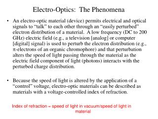
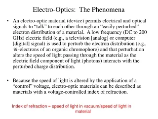
Electro-Optics: The Phenomena • An electro-optic material (device) permits electrical and optical signals to “talk” to each other through an “easily perturbed” electron distribution of a material. A low frequency (DC to 200 GHz) electric field (e.g., a television [analog] or computer [digital] signal) is used to perturb the electron distribution (e.g., p-electrons of an organic chromophore) and that perturbation alters the speed of light passing through the material as the electric field component of light (photons) interacts with the perturbed charge distribution. • Because the speed of light is altered by the application of a “control” voltage, electro-optic materials can be described as materials with a voltage-controlled index of refraction. Index of refraction = speed of light in vacuum/speed of light in material
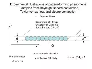
Electro-Optic Devices: The on-ramps & interchanges of the information superhighway • By slowing light down in one arm of the Mach Zehnder device shown below, the interference of light beams at the output can be controlled. Electrical information appears as an amplitude modulation on the optical transmission. This works equally well for analog or digital data. Electro-optic coefficient is the material parameter that defines how large an effect is observed for a given applied voltage • l = optical wavelength • n = index of refraction • r33= electro-optic coefficient • L = interaction length • = modal overlap integral d = electrode gap The Mach Zehnder Interferometer Vp = ld/(2n3r33LG) DC bias electrode ground electrode Modulated Light Out Light In RF electrode Substrate Vp is the voltage required to achieve signal transduction
Electro-Optic Behavior Depends on Orbital Type and Position Pi-electrons are more easily perturbed (displaced) than sigma-electrons
Electron Acceptor Electron Donor -conjugated bridge Example of common NLO chromophore design • PAS 38, a classical linear charge-transfer chromophore shows typical chromophore design; an electron donor and acceptor pair separated by a p-conjugated bridge
Example of an E-O Chromophore: A Charge Transfer (Dipolar) Molecule Charge displacement can occur over estended distances using materials with extended p-conjugation The charged separated form will have a larger dipole moment and thus a stronger interaction with an applied electric field
NONLINEAR OPTICAL EFFECTS: Microscopic and Macroscopic Polarization—Power Series Expansion • is the first nonlinear term, known as molecular first hyperpolarizability • For a symmetric molecule even order terms, and higher, are zero. • (2)represents material first nonlinear susceptibility • Oscillators (chromophores) must be aligned acentrically within the material to realize a nonzero (2)
The coefficient of the second term in the power series expansion of material Polarization in terms of applied electric fields, c(2), is given by r33 = bN<cos3q>(constant) Loading Parameter = N<cos3q> = (r33/b)(constant) r33 = electro-optic coefficient N = chromophore number density (molecules/cc) b = molecular first hyperpolarizability N<cos3q> = acentric order parameter *The constant depends on the dielectric properties of the material lattice
Optimization of Electro-Optic ActivityMacroscopic Level Electro-optic activity requires noncentrosymmetric chromophore symmetry, i.e., <cos3q> must be large Requires optimization of N<cos3q> *Statistical mechanics is the keyMolecular Level Requires optimization of b *Quantum mechanics is the key Let us first focus on the optimization of N<cos3q>, then we will consider the optimization of b.
E Field Top electrode Bottom electrode Use Electric Field Poling to Induce Noncentrosymmetric Order A DC poling field is applied across the chromophore / host matrix. Ideal case (no intermolecular interactions) : < cos3 θ> = E / 5kT
NONCENTROSYMMETRIC SYMMETRY REQUIRED FOR ELECTRO-OPTIC ACTIVITY Translating Microscopic to Macroscopic Electro-Optic Activity r33 = bN<cos3q>(constant) L = Langevin Function; W = Intermolecular Electrostatic Potential; k = Boltzmann constant; Ep is applied poling field; F is poling field felt by chromophore
EO Activity vs. Concentration: Theory & Experiment CLD in APC Statistical mechanical calculations permit understanding the role that chromophore shape has on macroscopic electro-optic activity
Loading Parameter = N<cos3q> r33/b(constant) Chromophore Shape Determines EO Activity Region of Enhanced Order
1 2 With a 2-1 aspect-ratio dipolar head-tail interactions are becoming predominant over side-side interactions Undesired Centrosymmetric Order Desired Noncentrosymmetric (EO active) Oder
Progress In Discotic Chromophores Relative r33 values for a series of modified bi(ProDOT) core in bridges. The more disc shaped, the more the dipole-dipole interaction are reduced. Prediction: OLD-4 can go to higher loading and still get improved electro-optic conversion. The wt% loading is based on core chromophore weight only.
Blends of Organic Molecular Glass Materials AJC-AJC (50%) HD/FD-AJC(75%) 400 AJC-AJC(75%) 350 HD/FD-AJC(50%) 300 HD/FD-AJC(23%) HD/FD 250 r33 (pm/V) 200 150 100 50 0 0 20 40 60 80 100 AJC146 AJC168 Poling field (V/um)
Multi-Chromophore-Containing Dendrimers Require the Use of Psuedo-Atomistic Monte Carlo Calculations to Simulate Poling-Induced Noncentrosymmetric Order Simulation requires consideration of Intermolecular electronic (e.g., dipole-dipole) interactions Intermolecular nuclear repulsive (steric) interactions Potential functions associate with rotation about covalent bonds Van der Waals interactions It is critical to reduce computation time by making logical approximations Treat pi-electron segments within the United Atom Approximation (Pi bonds prevent rotation and segments are thus rigid) Treat sigma-electron segments atomistically using correct bond rotation potentials
Examples of Monte Carlo Simulations Consideration of Various Modes of Attachment of Chromphore
D2.pas.41 VIII MC modeling in static DC field (Simulation of Results for Side-On Attachment Dendrimer) • Chromophores are the prolate ellipsoids. Solvent is assumed. Low Density 2% loading Simmulations performed by Harry Rommel and Bruce Robinson.
PAS Side-On Dendrite: High Density <cos3q> greater than 0.3
Discussion of Results Results are complicated as might be expected when multiple forces influence results Van der Waals interactions are clearly important in defining the order achieved in the preceding two figures Thus, results are not as simple as for the case of single chromophore dendrimers where the competition of electronic and nuclear intermolecular interactions dominate Covalent bond potentials do prevent dipole-dipole interactions from diving centrosymmetric ordering The two preceding slides clearly demonstrate that covalent bond potentials and nuclear repulsive (steric) interactions can result in order parameter increasing with concentration The next slide shows another possibility: The sum of interactions favors the noncentrosymmetric ordering potential component of the electronic intermolecular interactions
Center Optimum Monte Carlo Calculated Structure--Noncentrosymmetric Order By Design-- • Three chromophores (End-on attachment) -- 20 Debye dipole each • Best of Set of accepted M.C. moves. • Result: Near perfect order of 3 Chromophores • This is a limiting case: Very Large Field ( 3000 MV/m) Points on Z (up) Magic Angle Chromophore
Another Experimental Demonstration: Comparison of chromophore/APC composite with pure three arm chromophore dendrimer (D2PASS) The demonstration of the advantage of incorporating a chromophore into a multi-chromophore dendrimer is shown in the figure to the right. An electro-optic activity approximately three times greater than the best value that can be obtained for a chromophore/polymer composite is achieved.
Summary of Multi-Chromophore Dendrimer Results Electro-optic coefficients (at 1.3 microns wavelength) in the range 200-430 pm/V have been achieved with multi-chromophore containing dendrimers Ultimate electro-optic values (supermolecular structures) have not yet been achieved so values can be expected to become larger in the future Electro-optic activity can also been increased by inserting chromophores with greater molecular first hyperpolarizability into optimized supermolecular structures. We now turn our attention to optimizing chromophore hyperpolarizability
Comparison of Experimental Results and Theoretical Predictions Hyperpolarizability values relative to pNA measured by HRS and calculated by DFT. Electro-optic coefficients determined by simple reflection
Theoretical Prediction of Variation of Molecular First Hyper-polarizability and Dipole Moment with Chromophore Structure (Semi-Empirical Calculation Predictions)
Determination of Molecular 1st Hyperpolarizability (relative to CHCl3) by Femtosecond, Wavelength-Agile Hyper-Rayleigh Scattering (HRS) --Experiment confirms theoretical prediction-- bchloroform = 0.16 x 10⁻³⁰ esu[Kaatz et al, Opt. Commun. 157 (1998) 177] bchloroform = 0.49 x 10⁻³⁰ esu[Clays et al, Phys. Rev. Lett. 66 (1991) 2980]
Density Functional Theory (DFT) Calculations Predict The Same General Trends
Strategy for Improving NLO Chromophores: Choose the Right Combination of Donor, Bridge, and Acceptor With Theoretical Guidance
Summary Values of electro-optic activity greater than 300 pm/V (an order of magnitude greater than the commercial standard lithium niobate) have been realized for both single and multi-chromophore-containing dendrimers Much greater values can clearly be obtained by Using pseudo-atomistic Monte Carlo calculations to design dendrimers that lead to even larger values of N<cos3q> Using quantum mechanical calculations to design chromophores with improved molecular first hyperpolarizability, b. Values of greater than 1000 pm/V are likely possibility. Such materials would likely have a transformative impact on a number of technological areas