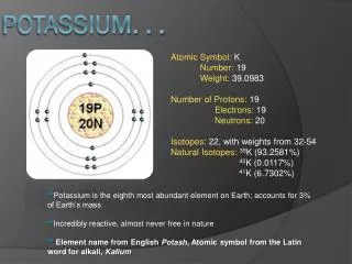
Potassium Channels
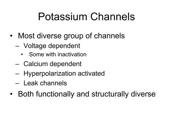
Missy Cavallin September 14, 2007. Potassium Channels. Outline. Types of K + channels Voltage-gated Functional roles Nomenclature Structure Activation Inactivation Assigned Experimental Papers (structure, voltage sensor, inactivation) . Types of K + Channels. Inward Rectifying

Potassium Channels
E N D
Presentation Transcript
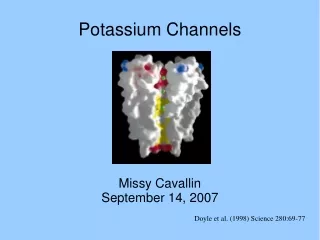
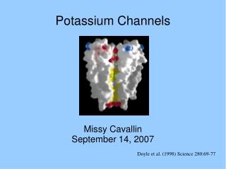
Missy Cavallin September 14, 2007 Potassium Channels Doyle et al. (1998) Science 280:69-77
Outline • Types of K+ channels • Voltage-gated • Functional roles • Nomenclature • Structure • Activation • Inactivation • Assigned Experimental Papers (structure, voltage sensor, inactivation)
Armstrong and Hille (1998) Neuron 20:371-380 Types of K+ Channels • Inward Rectifying • Ca+2 sensitive • ATP-sensitive • Na+ activated • Cell volume sensitive • Type A • Receptor-coupled • Voltage-gated
Inward Rectifying (KIR) • 2 transmembrane regions (M1 and M2) • 4 subunits form pore • P region between M1 and M2 • Regulated by concentration of extracellular potassium • Activity dependent on interactions with phosphatidylinositol 4,5-bisphosphate (PIP2) • Blocked by external Ba+
Functions of KIR • Maintain membrane resting potential near EK • non-conducting at positive membrane potentials • Contributes to cell excitability
Ca+2 sensitive • 4 protein subunits • Selectivity filter on external surface • RCK domains act as gate • 2 Ca+2 ions bind to RCK to regulate gate • 3 types of channels • High conductance (BK): 100-220 pS • Intermediate conductance (IK): 20-85 pS • Small conductance (SK): 2-20 pS
Functions of Ca+2 sensitive • Generate membrane potential oscillations • Afterhyperpolarization
ATP-sensitive • 2 Transmembrane regions • 4 subunits • Inhibited by ATP • Inwardly rectifying • Not voltage dependent
Functions of ATP-sensitive • Couples K+ conductance to cell metabolic state • Responds to metabolic changes: e.g. senses glucose concentration in -cells • Senses intracellular nucleotide concentrations
Na+ activated • Voltage-insensitive • Blocked by Mg+2 and Ba+2
Cell volume sensitive • Activated by increase in cell volume • Blocked by quinidine, lidocaine, cetiedil
Type A • Tetramer of -subunits and intracellular -subunits • Rapid activation and inactivation • Inactivation may involve -subunits • Possible role in delaying spikes by regulation of fast phase of action potentials
Receptor-coupled • Muscarinic-inactivated • Slow activation • Non-inactivating • Non-rectifying • Atrial muscarinic-activated • Inward rectifying
Voltage-gated channels: Function • Regulate resting membrane potential toward EK • Control shape and frequency of action potentials • Keep fast action potentials short • Terminate intense periods of activity • Time interspike intervals • Lower the effectiveness of excitatory inputs on a cell when open • Delayed rectifier type expressed in axons • Delayed activation and slow inactivation (shape action potential)
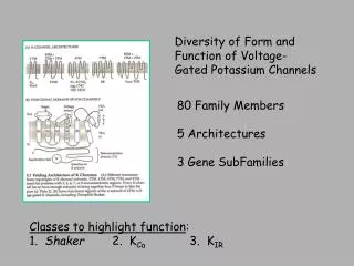
Gutman et al. (2005) Pharmacol Rev 57:473-508 Nomenclature of voltage- gated K+ channels
Voltage-gated: Structure • 6 transmembrane (TM) regions (S1-S6) • Principal subunits • Homo- or heterotetramers • S5 & S6 of each subunit surround pore • Auxiliary subunits • Regulate channel activity Gulbis et al (2000) Science 289:123-127
More Structure • S4 segment has multiple positively charged amino acids (arginine or lysine) • voltage sensor • P loop between S5 & S6 (selectivity filter) • G-Y-G sequence required for K+ selectivity • T1 domain: tetramerization domain; connects b subunits to a subunits
K+ movement through channel • K+ attracted to negative charge of helices near selectivity filter • K+ becomes hydrated before exiting channel Doyle et al. (1998) Science 280:69-77
Voltage-gated: Activation • Activated by depolarization • Voltage sensor (S4) • Translocation of charges on S4 • Helical screw • Lateral movement of crossed helices • Rocking motion at interface of 2 domains
Kurata and Fedida (2006) Progress in Biophysics and Molecular Biology 92:185-208 Voltage-gated: Inactivation • N-type: ball-and-chain • Amino acids at N-terminus occlude intracellular channel pore • Rapid inactivation • C-type • Conformational changes at selectivity filter or extracellular entrance to channel • Slow inactivation
Crystal Structure of a Mammalian Voltage-Dependent Shaker Family K+ Channel Stephen B. Long, Ernest B. Campbell, and Roderick MacKinnon Science (2005) 309:897-903 Paper 1
Methods • Kv1.2 with b2 subunit from rat brain expressed in yeast • X-ray crystallography • 2.9 Å resolution
Figure 1 A) Electron density map = blue mesh; final model trace = yellow B) Crystal lattice structure of channel: transmembrane segments of a subunit = red; b subunit + T1 = blue; unit cell = black box
Kv1.2 structural features • 4-fold symmetry (tetrad axis of unit cell) • Dimensions of tetramer: ~135 Å x 95 Å x 95 Å • Length of transmembrane segments: ~ 30 Å (approximately thickness of lipid bilayer)
Figure 2 A) Side view of ribbon model of channel with 4 subunits of unique color. NADP+ cofactor = black sticks B) 1 subunit from panel A illustrating S1-S6 as well as N- and C-termini C) Looking into pore from extracellular side to show interactions of 4 subunits.
Figure 3 A) Side view of 2 subunits of three voltage-gated K channels: Kv1.2 = red; KcsA = gray; KvAP = blue; outer = S5 of Kv1.2; inner = S6 of Kv1.2 B) Top view into pore Note the overlap of the structures (conserved).
How Does a Voltage Sensor Interact with a Lipid Bilayer? Simulations of a Potassium Channel Domain Zara A. Sands and Mark S.P. Sansom Structure (2007) 15:235-244 Paper 2
How is a positively charged S4 helix able to stably span the lipid bilayer? • Used molecular dynamics simulations to test the interactions of the voltage sensor domain of KvAP (archaebacterial) with an artificial phosphatidylcholine (PC) bilayer or with a more natural PC + phosphatidylglycerol (PG) bilayer • Computer modeling • Extended time (50 ns) vs. other models (20 ns) to increase sampling
Results • Penetration of water into center of voltage sensor and bilayer • Local deformation of bilayer due to interactions of lipid head groups with arginine side chains of S4 subunit • Electrostatic field is focused at center of bilayer • Numerous hydrogen bonds between phosphate head groups of lipids with arginine residues of S4 subunit
Figure 1 Lipids interact strongly with and are drawn into voltage sensor causing changes in PC bilayer conformation. A) Voltage sensor shown as ribbon (S1-3 = gray; S4 = magenta); lipid phosphate head groups colored based on z coordinate (red = extracellular; blue = intracellular). Arrow shows phosphate that is pulled away from surface. B) Arginines on S4 interactions with lipid phosphate groups.
Figure 2 Shows lipid bilayer compression when voltage sensor present vs. respected control bilayers without proteins. (distance between upper and lower phosphate atoms)
Figure 3 There are more hydrogen bonds formed in PC bilayer. Although both bilayers have hydrogen bonds between S4 arginines and lipid phosphate groups or water.
Figure 4 A and C) red = water; blue = lipid B) blue = cationic side chain; red = anionic side chain PC/PG overall has more hydrogen bonds. Increased hydrogen bonds at termini may stabilize charged S4 in bilayer. Lack of water to hydrogen bonds at R133 indicates prevention of water penetration.
Figure 6 A) Water in cavities of of voltage sensor but not at constriction point. B) Model of average pore radius. C) Electrostatic potential distribution (± 120 mV). Note the focus of electrical potential around salt bridge at constriction point.
Conclusions • Hydrogen bonding may help to stabilize voltage sensor in membrane • Compression of bilayer can decrease the distance necessary for the movement of C-type inactivation of potassium channels
Slow Inactivation in Voltage Gated Potassium Channels is Insensitive to the Binding of Pore Occluding Peptide Toxins Carolina Oliva, Vivian Gonzalez, and David Naranjo Biophysics Journal (2005) 89: 1009-1019 Paper 3
Toxin binding to K channels and Slow (C-type) Inactivation • Sensitive to K+ or tetraethylammonium (TEA) in pore • Mutations of external vestibule alter both processes • Does toxin binding interfere with C-type inactivation?
Figure 1 B) Amino acids important for toxin binding (left) and slow inactivation (right) overlap. red = scorpion toxin; yellow = conotoxin; orange = both; blue = slow inactivation
Methods • Oocytes • Whole cell recording • Outside-out patch recording • Toxins • Conotoxin (k-PVIIA) • Charybdotoxin (CTX)
Results • Rate of inactivation and recovery are toxin insensitive • Inactivation does not alter toxin binding site
Figure 2 Whole cell voltage clamp. A) Conotoxin (thick trace) decrease current amplitude and causes slight delay in activation. B) Time course of ratio of currents in panel A. Toxin binding (and current ratio) reached steady state within recording interval.
Figure 3 and Table 1 show that the inactivation kinetics are not affected by conotoxin in spite of change in current amplitude. Therefore, conotoxin binding is independent of slow inactivation. Similar results were shown for CTX (Fig. 6). There are differences between whole cell vs. outside out patches, but not with regards to toxin effects.
Figure 5 A) Conotoxin decreases current amplitude in response to voltage steps. B) IV and GV relationships. Voltage shift does not change in the presence of toxin (bottom). DV = -18 mV for no toxin; DV = -21 mV with toxin
Conclusions • Inactivation kinetics were not affected by toxin binding • Bound toxin does not hinder conformation change involved with slow inactivation