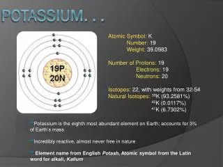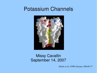
Potassium Channels
Potassium Channels. Roger Thompson BSC5936 Membrane Biophysics Spring 2005 Florida State University. Evolution of the superfamily of voltage-gated channels. Armstrong & Hille (1998)Neuron 20: 371-380. Structure. Inner & Outer membrane face Layers of aromatic amino acids Tryptophan


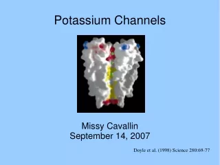
Potassium Channels
E N D
Presentation Transcript
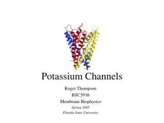
Potassium Channels Roger Thompson BSC5936 Membrane Biophysics Spring 2005 Florida State University
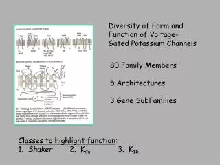
Evolution of the superfamily of voltage-gated channels. Armstrong & Hille (1998)Neuron 20: 371-380
Structure • Inner & Outer membrane face • Layers of aromatic amino acids • Tryptophan • Tyrosine • Forms cuff around pore • Pulls pore open like springs
More structure • Two gating theories • Ball and chain • Paddle • Selectivity filter • A narrow region near outer face of membrane • Contains glycine-tyrosine-glycine residues • Is lined with carbonyl backbone • Ions travel through in single file
Ball and Chain Theory When the channel is open (center), any one of the four inactivation balls can inactivate the channel (right). Inactivation for a Na+ channel is similar, but there is a single inactivaton ball. Armstrong & Hille (1998) Neuron 20:371-380
Structure of voltage-gated ion channels. Functional components (A) and peptide folding (B) are shown diagrammatically with P regions in red and the S4 segment in pink. Armstrong & Hille (1998)Neuron 20: 371-380
Putative membrane topologies of K+ channel subunits. A) voltage-gated K+ channel. B) the KATP channel Papazian (1999) Neuron 23: 7-10
Cross section of the P region, S5, and S6 of a K+ channel. Armstrong & Hille (1998)Neuron 20: 371-380
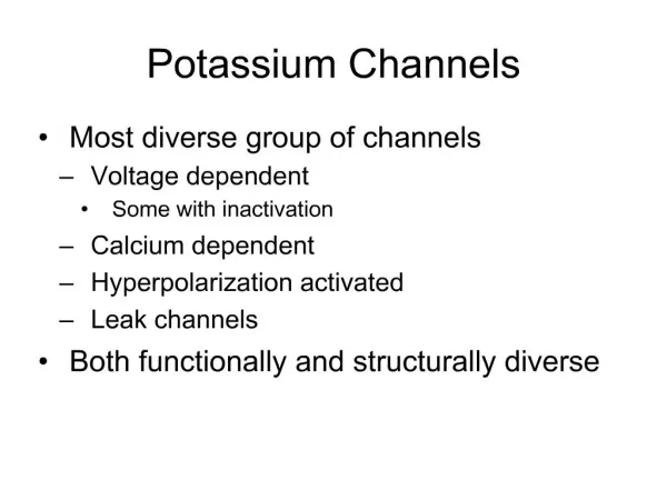
Types of K+ Channels • Voltage-gated • Inward Rectifying • Ca2+ sensitive • ATP-sensitive • Na+ activated • Cell volume sensitive • Type A • Receptor-coupled
Voltage-gated • 6 transmembrane domains • 4 subunits surround central pore (S5 & S6 regions of each subunit • Selectivity filter (P region) • Hydrophobic sequence between last 2 TMD; contains Gly-Tyr-Gly • Voltage sensor (S4) has multiple positively charged amino acids
Voltage-gated con’t • Activated by depolarization • Present in both excitable and nonexcitable cells • Functions • Regulate resting membrane potential • Control of the shape and frequency of action potentials
Composite model of a voltage-dependent K+ channel. The subunit is shown in red and the subunit in blue. Gulbis etal., (2000) Science 289: 123-127
KirBac1.1 structure consisting of an all -helical integral membrane section plus an intracellular domain consisting mostly of -sheet. Kuo etal., (2003) Science 300: 1922-1926
Functions of Delayed Rectifier K+ Channels • Delayed activation; slow inactivation • Allows efficient repolarization after action potential • Structure: tetramer of -subunits subunits • Can be blocked by • 4-aminopyridine, Dendrotoxins, Phencyclidine, Phalloidin, 9-aminoacridine, Margatoxin, Imperator toxin, Charybdotoxin
Inwardly Rectifying K+ Channel • 2 transmembrane regions (M1 & M2) • Corresponds to S5 & S6 in Kv channel • 4 subunits surround central pore • P region separates M1 and M2 • Non-conducting at positive membrane potentials • Blocked by external Ba++
Functions of Inward Rectifier K+ Channels • Maintains resting membrane potential near Ek • Contributes to cell excitability • Non-conducting at (+) membrane potentials
Ca2+ Sensitive K+ Channels • Generate membrane potential oscillations • 4 protein subunits • External surface contains selective K+ filter • Inner cavity accommodates a hydrated K+ ion • 2 Ca2+ ions binds to RCK domains;interact & regulate gate
3 Types Ca2+ Sensitive K+ Channels • High conductance (BK) channels • Gated by internal Ca2+ and membrane potential • Conductance = 100 to 220 picoSiemens (pS) • Intermediate conductance (IK) channels • Gated only by internal Ca2+ • More sensitive than BK channels • Conductance = 20 to 85 pS • Small conductance (SK) channels • Gated only by internal Ca2+ • More sensitive than BK channels • Conductance = 2 to 20 pS
ATP-sensitive K+ Channels • ATP-inhibited • Inwardly rectifying • pH sensitive • Tetramer of 2 TM domains • Functions as glucose sensor in -cells • Blockers include Lidocaine
Na+ Activated K+ Channels • Voltage-insensitive • Blocked by Mg++ or Ba++
Cell Volume Sensitive K+ Channels • Activated by increased cell volume • Blocked by Lidocaine
Type A K+ Channels • Possible regulation of fast repolarizing phase of action potentials: delay spiking • Tetramer of -subunits + intracellular -subunits • -subunits may confer rapid inactivation • Blockers include Phencyclidine and Dendrotoxins
Receptor-coupled K+ channels • Blockers include Ba++, Bradykinin, Cs+, TEA and Quinine • Two types • Muscarinic-inactivated • Slow activation • Non-inactivating • Non-rectifying • Atrial muscarinic-activated • Inward rectifying Muscarinic = acetylcholinergic
Additionally • Greater tendency to allow K+ to flow into cell than to flow out • Regulated by extracellular K+ concentration • Inward rectification due mainly to internal magnesium block of outward current • Dependent on interaction with phosphatidylinositol 4,5-bisphosphate (PIP2)
Paper 1 The structure of the potassium channel: Molecular basis of K+ conduction and selectivity Doyle et al. (1998) Science 280:69-77
How determined? • X-ray crystallography and site-directed mutagenesis • Data refinement to 3.2Å
Findings • Inverted teepee shape • Selectivity filter diameter = 12Å • Carbonyl O2 line selectivity filter • K+ is 10.000x more permeable than Na+ • Both side of pore are (-) charged • The pore is hydrophobic
Fig. 3 Inverted teepee architecture of the tetramer. Doyle etal., (1998)Science 280: 69-77
Fig. 3 Stereoview of a ribbon representation illustrating the three dimensional fold of the KcsA tetramer viewed from the extracellular side. The four subunits are distinguished by color. CS :Streptomyces lividans Doyle etal., (1998)Science 280:69-77
Fig. 3 Stereoview perpendicular to membrane. Carboxyl orientation shown in white. Doyle etal., (1998)Science 280: 69-77
Fig. 3 Ribbon representation of the tetramer as an integral-membrane protein. Aromatic amino acids are displayed in black. Doyle etal., (1998)Science 280: 69-77
Fig. 7 Two mechanisms by which the K+ channel stabilizes a cation in the middle of the membrane. First, a large aqueous cavity stabilizes an ion (green) in the otherwise hydrophobic membrane interior. Second, oriented helices point their partial negative charge (carboxyl end, red) towards the cavity where a cation is located. Doyle etal., (1998)Science 280: 69-77
Fig. 4 A cutaway stereoview displaying the solvent-accessible surface of the K+ channel colored according to physical properties. Blue – high positive charge; Red – negative charge Yellow – hydrophobic C atoms; Green – K+ ion positions; White – neutral charge Doyle etal., (1998)Science 280: 69-77
Fig. 4 A three-dimensional stick model representation of the minimum radial distance from the center of the channel pore to the nearest van der Waals protein contact. Doyle etal., (1998)Science 280: 69-77
Paper 2 Contribution of the S4 segment to gating charge in the Shaker K+ channel Aggarwal & MacKinnon (1996) Neuron 16:1169-1177
Hypothesis testing • Used Shaker K+ channels expressed in Xenopus oocytes • Neutralized positive charges in the S4 segment • Measured reduction in gating charge. • This reduction would represent the contribution of the positively charged residue to the gating charge of the channel
How tested? • Mutagenesis to create AgTX combined with tritiated N-ethylmaleimide • Based on extinction coefficient of nontritiated NEM-labeled AgTX, the specific activity of radiolabeled toxin was determined by measuring disintegrations per min as a function of toxin concentration
Fig. 2 • Fraction of channels bound by inhibitor (circles) and fraction blocked (triangles) at different concentrations of radiolabeledAgTX1D20C and unlabled AgTX, respectively. • Tritiated AgTX1D20C binding data for oocytes expressing Shaker K+ channels. U = uninjected, I = oocytes expressing channels, C= 40X conc. Injection of unlabeled AgTX Aggarwal & MacKinnon (1996) Neuron 16:1169-1177
Fig. 3 B) Repolarization-induced currents integrated over time to give total charge, and plotted as a function of pulse potential (Q-V). Dashed line= linear capacitance of the cell and voltage clamp system; nonlinear component = gating charge movement D) Q-V plot of repolarization-induced current is linear. Aggarwal & MacKinnon (1996) Neuron 16:1169-1177
Fig. 3 E) Correlation plot mapping total gating charge (q) in electron charge units as a function of total channel number (n) for several oocytes expressing Shaker K+ channels. The line corresponds to a linear regression fit using the method of least squares with a 95% confidence interval. Aggarwal & MacKinnon (1996) Neuron 16: 1169-1177
Fig. 7 Gating charge movement (q/n) for the wild-type Shaker K+ channel and charge-neutralizing (B) and charge-conserving (C) S4 mutations as a function of pulse potential. D) A model of Shaker K+ gating in which the S4 segment undergoes a change in secondary structure. Aggarwal & MacKinnon (1996) Neuron 16:1169-1177
Paper 3 The orientation and molecular movement of a K+ channel voltage-sensing domain Gandhi et al. (2003) Neuron 40:515-525
What? • New model of voltage sensing domain • where S4 lies in the lipid, at the channel periphery • and moves through the membrane • as a unit with a portion of S3
How tested? • By accessibility of thiol-reactive probes • Tetramethylrhodamine maleimide (TMRM) • Methanethiosulfonate (MTS) reagents • MTSET and MTSES • Disulfide scanning experiments
Conclusions • found that the S1-S3 helices have one end that is externally exposed • that S3 does not undergo a transmembrane motion • and S4 lies in close apposition to the pore domain in the resting and activated state
Fig. 1 • KvAP structure and the activated state paddle model labeled to indicate several sites examined for S-S bonds formation between S4 and the pore domain and for state-dependent accessibility to MTS reagents. • Cartoon representation of the resting and activated state paddle model. Gandhi etal., 2003 Neuron 40:515-525
Fig. 3 Disulfide bond formation between S4 and the pore region. Gandhi etal., 2003 Neuron 40: 515-525
Fig. 4 Disulfide bond between position 355C and 422c eliminates gating current. Gandhi etal., 2003 Neuron 40:515-525
Fig. 5 Disulfide bonding to S5 depends on the location of the S3-S4/S4 cysteine and on the gating state. Gandhi etal., 2003 Neuron 40:515-525