Download
1 / 49
630 likes | 1.21k Vues
Introduction to ADAMS. Course manual for Multibody Dynamics A, wb1310 Martijn Wisse 29th december 1999 revised for V2005.0.0 by Bram Soethoudt May 2005. Contents. 1 Example 3

E N D
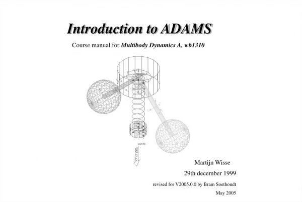
Introduction to ADAMS Course manual for Multibody Dynamics A, wb1310 Martijn Wisse 29th december 1999 revised for V2005.0.0 by Bram Soethoudt May 2005
Contents 1 Example 3 2 Program Overview 15 3 Layout & View Control 19 4 Parts & Geometry 23 5 Joints & Motion generators 26 6 Markers 30 7Springs& Force generators 31 8 Simulations & Animations 35 9 Plotting & Measures 41 10 Tips & Useful Tools 45 Contents
Creating a new model • Start ADAMS-View: Data Analysis & Simulation Software Adams 12.0 Aview ADAMS-View • Use the startup dialogbox or from the Menu-bar select Build Model New… • Change the Model Name to ‘example_1’ • Click OK, ADAMS is now ready to construct a model Example
Environment Settings • To set gravity and units settings: • From the Menu-bar select Settings Gravity… • In the Gravity Settings window check the Gravity checkbox • Apply • From the Menu-bar select Settings Units… • Select Example
Creating a new link • In the Main Toolbox click the icon Rigid Body: Link • Check options Length, Width and Depth, • Fill in desired dimensions: ‘(373mm)’, ‘(6mm)’ and ‘(6mm)’ • * Hit return after entering the dimensions • * Notice instructions in lower left corner of screen • Pick location of first end of link • Pick second location to define orientation of link Example
Creating a new joint • In the Main Toolbox click the icon Joint: Revolute • Select construction options: • - 1 Location • - Normal to grid • Pick the location of the revolute joint on an existing rigid body Example
Naming the model elements • Right click on the created link • Select Part: Part_1 Rename • Change name into ‘.example_1.pendulum’ • Repeat procedure for the created joint • Rename joint as ‘.example_1.hinge’ Example
Naming the view window • From the Menu-bar selectView View Accessories... • In the View Accessories window type your id • Click Enter • Close View Accessories window • Your id appears in the upper left corner of the model view window Example
Rotating model elements • In the Main Toolbox select the Select-tool • Left click on the pendulum to select • In the Main Toolbox select the Center-tool • Center the view at the hinge • In the Main Toolbox select the Position-tool • Rotate the pendulum 30 degrees Example
Saving the model • From the Menu-bar selectFile Export • In the File Export window right click at File Name • Select Browse... • Save model as ‘example_1.cmd’ in the File Selection window • In the File Export window click OK • Save your work frequently Example
Loading a model • From the Menu-bar selectFile Import • In the File Import window right click at File To Read • Select Browse... • Open existing ‘.cmd’ - file • * Note: if the model was already loaded, a number of errors appears Example
Running a simulation • In the Main Toolbox select the Simulation-tool • Change the number of steps into ‘100’ • Left click the Start or continue simulation button • To simulate again, first press the Reset to input configuration button • * Note: The viewport shows the simulation; to return to the model view, left click the Select-tool • * Note: The simulated motion is stored, and available for animation or plotting Example
Plotting simulation results • In the Main Toolbox select the Plotting-tool • For the Object to plot choose Constraint hinge Ax_Ay_Az_Projection_Angles Z • Click Add Curve • Double-clickPage_1 and click on Plot_1 • Add Title and insert your id as Subtitle • Click OK Example
Simulation results • Print your graph • To leave the Plot Window click Return to modeling environment • This is the end of the example Example
The ADAMS interface The ADAMS interface consists of two main windows: - the View Window, displaying your current model - the Main Toolbox Most common ADAMS functions can be accessed through the Main Toolbox. All functions can also be found under the the Menu bar in the View Window. Title Main Toolbox Modeling and simulation tools Right click to open individual tool stacks Container Display changes depending upon the tool selected from the tools above Menu Bar Working Grid Coordinates Window Triad Instruction Bar Program Overview
ADAMS Online Help ADAMS has an extensive online help facility in HTML and PDF format. Most documentation on model construction is to be found under ADAMS/View. Program Overview
The ADAMS model hierarchy Database Construction points Model Plot GUI Geometry Results Set Component Curve Part Analysis Force Measure Constraint Simulation Output Model Elements More... Do not get saved in model command file format (.cmd) (See next Page for explanation) Marker The model element naming is consistent with the hierarchy (e.g. model_name.part_name.geometry_name or model_name.joint_name) Program Overview
File Handling in ADAMS The two most common formats in which models in ADAMS can be saved are: • 1 ADAMS/View Database files (.bin) • Include the entire modeling session including models, simulation results, plots, etc. • Are large binary files • 2 ADAMS/View Command files (.cmd) • Includes only the model elements and their attributes • Are relatively small, editable text files The other formats in which data in ADAMS can be imported and exported are: • ADAMS/Solver Input files (.adm) • Geometry files (STEP, IGES, DXF, DWG, Wavefront, stereolithography) • Test and Spreadsheet data files • Simulation results files (.msg, .req, .out, .gra, .res) Program Overview
View settings • View settings from the Main Toolbox: • Background Color • Triad visibility (the global coordinate system displayed in the lower left corner of the View Window) • View layout • Icon appearance: double click on the Icons button • Setting the View Title: • From the Menu-bar choose View View Accessories • Set your id as View Title in the View Accessories window Layout & View Control
Viewpoint controls The Viewpoint can be controlled from the Main Toolbox. Click the Select-tool and use the following view controls: Fit Rotate Window zoom Pan Center Zoom And the preset view orientations: Front Right Top Isometric Layout & View Control
Setting Object Appearances • The appearance of a displayed object can be altered when the object is selected (highlighted): • color: From the Menu-bar select Edit Appearance • change Color by right-clicking the Color-field • render mode: From the Menu-bar select View Render Mode • toggle render on/off in the Main Toolbox Layout & View Control
The Working Grid • The Working Grid is used: • as a plane for creating objects • to draw, move, resize, reshape geometry by snapping to grid • Change Working Grid settings by double-clicking the Grid-button • on the Main Toolbox (first apply the Select-tool) • When creating a new model element, first set the Working Grid with the • correct location and orientation. • Set the location of the Grid origin by: • global origin, or • pick location • Set the orientation as one of the principal planes: • Global XY, • Global YZ, or • Global XZ Layout & View Control
Creating Parts & Geometry • Each rigid body in ADAMS is modeled as a part. Each part has one or more geometries. To create a new part, start with a geometry, e.g. a box or a cylinder. • To create a new geometry: • In the Main Toolbox right-click on Rigid Body • Select the appropriate geometry: • Link Sphere • Box Torus • Cylinder • Choose New Part or Add To Part • Enter required dimensions • Follow instructions in lower left corner of screen • * When adding a geometry to an existing part, check the position of the automatically generated ‘Center of Mass’-marker Parts & Geometry
Positioning Objects Reposition objects relative to viewing coordinates Reposition objects relative to the working grid Translate from an initial location to another Rotate about or align with grid or features Position objects by aligning faces Rotation: Translation: Parts & Geometry
Modifying Part Properties • To modify Mass and Inertia properties of a part: • Right-click on the part to be modified • ADAMS/View displays the names of all model elements near the cursor • Select the part to be modified and then select Modify • In the Modify Rigid Body window enter the user specified mass and inertia values • To modify the name of the part: • Select the part to be modified and then select Rename Parts & Geometry
Joints • In ADAMS joints are used to connect rigid bodies to each other or to the ground with a limited number of degrees of freedom. • To create a new joint: • Both parts to be connected by the joint should already exist • In the Main Toolbox right-click on Joint • Choose the appropriate joint: • revolute • translational • Choose a connection between one part and the ground: 1 location, or between two parts: 2 Bod - 1 loc • Choose the orientation of the joint by setting the axis for the degree of freedom: • - normal to the Working Grid - in a direction indicated with the mouse • Follow instructions in lower left corner of screen Joints & Motion Generators
Creating a Motion Generator • A degree of freedom in a joint can be replaced by a prescribed motion. A motion can be defined as displacement, velocity or acceleration as a function of time. • To create a motion generator: • A joint should already exist • In the Main Toolbox right-click on Rotational Joint Motion • Choose the type of motion, equal to the degree of freedom allowed by the joint: • rotational, or • translational • Enter the desired constant velocity • * When applying a rotational velocity, enter the letter d to ensure that ADAMS uses as units degrees/second • Follow instructions in lower left corner of screen • If an other motion function than a constant speed is desired, modify the motion generator afterwards Joints & Motion Generators
Motion Generators with non-constant velocity • The prescribed motion of a motion generator can be a complex function of time. First, a motion generator with constant velocity must have been created. • To modify the motion function: • Select the motion generator and then select Modify • In the Impose Joint Motion window select the type of motion generator • Right-click in the ‘F(time)=’-field • Select Function Builder… • Define a runtime function, using ‘time’ as independent variable, or • Enter a more complex predefined function (next page) Joints & Motion Generators
The Function Builder • To enter a complex mathematical function of time for the motion generator: • In the Function Builder window select the desired math function • Use the Assist… dialog box • Use the Verify button before closing the Function Builder * Note: The Function Builder cannot read lines over 80 characters long * Note: If the function is new to you, see the description in the Help Joints & Motion Generators
Markers • In ADAMS, important geometrical points on a rigid body are represented by Markers. A marker is a massless entity, only possessing a location and an orientation. When a new rigid body or joint is created, ADAMS automatically creates the necessary markers (e.g. the ‘Center of Mass’-marker). • When a spring or other force must be attached at a previously undefined location on a part, first a new marker must be created. • To create a new marker: • In the Main Toolbox right-click on Rigid Body • Select Marker • Choose Add to Ground or Add to Part • For the orientation of the marker, choose one of the principal planes: • - Global XY • - Global YZ • - Global XZ • Follow instructions in lower left corner of screen Markers
Spring/Damper • To create a spring/damper combination: • Two markers on different parts should already exist for spring attachment • In the Main Toolbox choose Connector: Translational Spring-Damper • Check applicable properties and enter user-specified values • Follow instructions in lower left corner of screen • To change properties and graphic representation: • Select spring to be modified and then select Modify • * Note: in order to see the diameter ratio option, load the <Sayfield> menu from the menu bar Springs & Force Generators
Applied Force: Torque • To create an applied torque on a rigid body: • A marker should already exist as point of application for the torque • In the Main Toolbox right click on Connector • Select Applied Force:Torque (single component) • Choose a Runtime Direction and Construction (initial direction) • Choose Characteristic: - a simple force, or • - a to be defined complex custom function • Follow instructions in lower left corner of screen • To alter the force function: • Right-click on the torque and select Modify • In the Modify a Torque window right click in the ‘F(time,…)’-field • Use the Function Builder • * Note: In contrast with a motion generator, an applied torque can be a function of positions of objects Springs & Force Generators
Special Force: Tire A tire is represented in ADAMS as a special type of force. This special force automagically generates a part for the wheel. • To create a new tire: • In the Main Toolbox right click on Connector and select Tire • In the Create Wheel and Tire window enter the following data: • Enter Name • Enter user specified Mass and Inertia properties • Enter the required Tire Property File • Enter the required Road name (create if it does not exist) • Enter Location of the cm and Orientation of the wheel axis: default (0,0,0) is the wheel axis along the z-axis Springs & Force Generators
Creating a Road A tire in ADAMS needs a road. Multiple tires can use one road. • To create a new road: • In the Create Wheel and Tire window right click on Road and select Create • In the Create Road window enter the following data: • Name • Part that the road is attached to (usually ground) • the required road Property File • adjust the Euler Angles to (0,-90,0) for the plane y=0, contact if y<0 Springs & Force Generators
Debugging • Before running a simulation, you should check your model; are all parts connected as intended? • To check the number of Degrees of Freedom: • use the Verify tool in the lower right corner of the screen • the Information window displays the number of degrees of freedom, the number of moving parts and the number of joints Simulation & Animation
Running a simulation • To run a simulation: • In the Main Toolbox select the Simulation-tool • Select Default analysis • Enter the desired End Time or Duration • Enter the desired integration Step Size or Number of Steps • Select the Debug option, ADAMS shows the Maximum Equation Error window • Use the Start, Stop and Rewind buttons • To access advanced simulation settings, apply … (More) • See (next page) Simulation & Animation
Simulation Settings • Advanced Simulation Settings: • In the Main Toolbox select the Simulation-tool, then select …(More) • To find static equilibrium, apply • To perform a linear modes analysis, first find static equilibrium, then apply, In the Linear Modes Controls window use , and to display and animate the eigenfrequencies and eigenmodes • To change the integration accuracy, apply Simulation Settings… Simulation & Animation
Assemble Default* Linear Static* Dynamic* Kinematic* Types of Virtual Simulations in ADAMS Assembly Operation Linear Non-Linear Eigensolution or State Matrices Motion Study Equilibrium Calculation(s) Non-Linear DOF=0 DOF>0 *Automatically performs an assembly operation Simulation & Animation
Basic Animation Control After Performing a simulation, the Animation Container on the Main Toolbox can be used to control the animation Play-forward Stop Animation Step Backward Play-reverse Step Forward Reset to Frame 1 Modify Animation View Frame Slider Fixed Base: camera is fixed on the ground Base Part: camera is fixed on the CM of the part Base Point: camera is fixed on the selected CSM Drag until the required frame is reached Loop Function Select to replay animation indefinitely Advanced Animation features Simulation & Animation
Animation and Rendering • ADAMS has a built-in movie generator, which produces computer animations in .AVI-format. • To make an .AVI-movie: • After running a simulation, select View Load Animation from the Plotting Main Menu • Select desired view with the View Control toolbars or right click in main window • If desired adjust settings for Animation, View, Camera, Record, Overlay, Contours • Press record and press play to start the recording • Movie is saved in working directory (default is L:\) Simulation & Animation
Overview of the Plot Plotting main menu Plotting toolbar Manage pages of plots Return to modeling Plot formatting Plot location Plotting & Measures
Overview of the Plot Builder Displays list of current simulations Manages curves of plots Detailed List of Output Parameter to plot against Types of results to be displayed: Objects, Measures, Requests and Results Plotting & Measures
Useful Plot functions Useful functions in the Plot Window: Display Plot Statistics Zoom Return to modeling environment Useful functions in the Plot Builder: Surf; automatically clears and updates plots as items are selected Data filter Plotting & Measures
Creating Measures in ADAMS To create measures… 1 Use the Main Menu Build| Measure can be used for all measures 2 Use the Measure Tool Stack on the Main Toolbox can be used for point-to- point and included angle measures 3 Use the right mouse button and select Measure from the pop-up menu can be used for object and point measures Plotting & Measures
Tips & Tricks • Some general tips & tricks: • Use the Escape key to abort a command. • Press ‘Enter’ after input to make sure that the new value is set. • Edit Copy generates a copy at the same location as the original. Right-click on the model to select the copied element. • Right click on any field for suggestions or options. Tips & Useful Tools
Navigating through a Modeling Database Use the Database Navigator to view and select objects in a modeling database To open the Database navigator… Use the menu bar Tools| Database Navigator Execute an editing command when no object is selected “+” indicates existence of hidden children “-” indicates all children objects are displayed The Database Navigator only displays those types of objects that are appropriate for the command you are executing Tips & Useful Tools
Using the Command Navigator Use the command Navigator to enter ADAMS/View commands without knowing the entire command syntax The Command Navigator… • displays a list of all the ADAMS/View command keywords • corresponds to the matching menus available in previous versions of ADAMS/View • lets users perform advanced commands not immediately accessible • helps users learn the command syntax when customizing ADAMS/View “+” indicates existence of hidden command levels “-” indicates that the next command level is currently displayed No indicator- when selected, a dialog box appears in which you enter values to execute the command Tips & Useful Tools
Display parent and child information Set the information mode Display a text file Display object information Display an object’s modify dialog box Clear information window Save information to a text file Copy text Using the Information Window The Information window displays different types of information about a model Tips & Useful Tools
Using the Select List Manager The Select List manager is used to… get a list of selected objects add/remove objects from a list work with multiple geometries Tips & Useful Tools