Velocity U
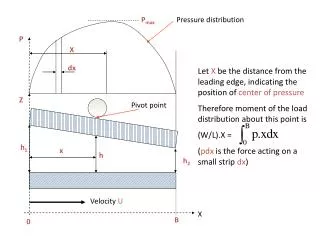
P max. Pressure distribution. P. X. dx. Let X be the distance from the leading edge, indicating the position of center of pressure Therefore moment of the load distribution about this point is (W/L).X = ( pdx is the force acting on a small strip dx ). Z. Pivot point. h 1. x. h.

Velocity U
E N D
Presentation Transcript
Pmax Pressure distribution P X dx Let X be the distance from the leading edge, indicating the position of center of pressure Therefore moment of the load distribution about this point is (W/L).X = (pdx is the force acting on a small strip dx) Z Pivot point h1 x h h2 Velocity U X B 0
Tilting pad bearing – center of pressure Non-dimensionalizing and writing p as , x as x*B, and W* as , we get Or , which on solving gives It is seen that the value of X/B is determined by the value of K which is determined by the value of h1/h2 = 1+K
Tilting pad bearings – flow rate The Reynold’s equation for oil flow gives: considering flow only in the x-direction We know that when dp/dx = 0, h = ho, therefore Also ho = h2A = ho.2(1+K)/(2+K) where K=(difference of inlet and outlet film thickness)/(outlet film thickness) Thus Therefore knowing the inlet and outlet film thicknesses, we can determine the flow rate
Tilting pad bearing - friction • The shear stress on each surface is given by the formula (for a Newtonian viscous fluid) • It was earlier shown that • Where U1 is the velocity at z = h and U2is the velocity at z = 0. In the current discussion of thrust pads, U1 = 0 and U2 is called U • Therefore
Tilting pad bearing - friction • Therefore stress on fluid layer when z=0 is • Stress when z = h is • The friction F of the pad is the integral in the x and y directions of the shear stress t, i.e. • Where L and B are the extent of the pads in the y and x directions respectively
Tilting pad bearing- friction calculation • Therefore we get • Integrating term by term, remembering that h and U are constant and h is a function of x only, integrating by parts we get • p is 0 at x = 0 and x = B. Therefore only the 2nd term in the above equation remains
Normal load as a function of pressure • Therefore we have as h = h2(1+K-Kx/B), and dh= -(h2K/B)dx • It is obvious that the total load, so
Tilting pad- friction (contd.) Integrating the 2nd term in the friction expression We get Therefore the friction expression becomes The negative sign in the 1st. Term indicates that the friction force is in a direction opposite to that of the velocity
DUCOM MICHELL Tilting pad apparatus in the lab Features • Measurement of pressure distribution along and across the line of flow • Measurement of temperature at pressure points • Continuously variable sliding speed • Independent gap setting at leading and trailing edge • Oils with different viscosity can be tested to determine the effect of viscosity on other variables Therefore it can be used to determine the inter-dependence of the different variables
Picture of apparatus Manometer tubes showing pressure