Download
1 / 21
210 likes | 300 Vues
Learn about resistance, ohmmeters, current, voltage, ammeters, and voltmeters in electrical circuits. Understand the principles of conductance and resistor types. Explore color coding and resistor values.

E N D
Current and Voltage ET 162 Circuit Analysis Electrical and Telecommunication Engineering Technology Professor Jang
Acknowledgement I want to express my gratitude to Prentice Hall giving me the permission to use instructor’s material for developing this module. I would like to thank the Department of Electrical and Telecommunications Engineering Technology of NYCCT for giving me support to commence and complete this module. I hope this module is helpful to enhance our students’ academic performance.
OUTLINES • Resistance and Conductance • Ohmmeters • Current and Voltage • Ammeters and Voltmeters Key Words: Resistance, Ohmmeter, Current, Voltage, Ammeter, Voltmeter ET162 Circuit Analysis –Current and Voltage Boylestad 2
Introduction to Resistance The flow of charge through any material encounters an opposing force similar in many aspect to mechanical friction. This opposition, due to the collisions between electrons and other atoms in the material, which converts electrical energy into another form of energy such as heat, is called the resistance of the material. The unit of measurement of resistance is the ohm (Ω). Figure 1.1Resistance symbol and notation. ET162 Circuit Analysis –Current and Voltage Boylestad 3
l r = R (ohms, Ω) A At a fixed temperature of 20°C (room temperature), the resistance is related to the other three factor by ρ: resistivity of the sample (CM-ohms/ft at T=20°C) l : the length of the sample (feet) A : cross-sectional area of the sample (circular mils (CM)) FIGURE 1.2Factors affecting the resistance of a conductor. ET162 Circuit Analysis –Current and Voltage Boylestad 4
Resistance: Circular Wires • For two wires of the same physical size at the same temperature, • the higher the resistivity (ρ), the more the resistance • the longer the length of a conductor, the more the resistance • the smaller the area of a conductor, the more the resistance • the higher the temperature of a conductor, the more the resistance FIGURE 1.3 Cases in which R2 > R1. For each case, all remaining parameters that control the resistance level are the same. ET162 Circuit Analysis –Current and Voltage Boylestad 5
Types of Resistors – Fixed Resistors Resistors are made in many forms, but all belong in either of two groups: fixed or variable. The most common of the low-wattage, fixed-type resistors is the molded carbon composition resistor. FIGURE 1.3Fixed composition resistor. The relative sizes of all fixed and variable resistors change with the power rating, increasing in size for increased power ratings in order to withstand the higher currents and dissipation losses. FIGURE 1.4Fixed composition resistors of different wattage ratings. ET162 Circuit Analysis –Current and Voltage Boylestad 6
Types of Resistors – Variable Resistors Variable resistors have resistance that can be varied by turning a dial, knob, screw, or whatever seems appropriate for the application. FIGURE 1.5Potentiometer: (a) symbol: (b) & (c) rheostat connections; (d) rheostat symbol. ET162 Circuit Analysis –Current and Voltage Boylestad 7
Color Coding and Standard Resistor Values A whole variety of resistors are large enough to have their resistance in ohms printed on the casing. However, some are too small to have numbers printed on them, so a system of color coding is used. FIGURE 1.6Color coding of fixed molded composition resistor. The first and second bands represent the first and second digits, respectively. The third band determines the power-of-ten multiplier for the first two digits. The fourth band is the manufacture’s tolerance.The fifth band is a reliability factor, which gives the percentage of failure per 1000 hours of use. Table 1Resistor color coding. ET162 Circuit Analysis – Voltage and Current Boylestad 8
Ex. 1-1 Find the range in which a resistor having the following color bands must exist to satisfy the manufacturer’s tolerance: a. 82Ω ± 5% (1% reliability) Since 5% of 82 = 4.10, the resistor should be within the range of 82Ω ± 4.10Ω, or between 77.90 and 86.10Ω. b. 3.9Ω ± 10% = 3.9Ω ± 0.39Ω The resistor should be somewhere between 3.51 and 4.29Ω. ET162 Circuit Analysis –Current and Voltage Boylestad 9
1 = G (siemens, S) R A = G r × l Conductance The quantity of how well the material will conduct electricity is called conductance (S). Indicating that increasing the area or decreasing either the length or the resistivity will increase the Conductance. (S) ET162 Circuit Analysis –Current and Voltage Boylestad 10
Ex. 1-2 What is the relative increase or decrease in conductivity of a conductor if the area is reduced by 30% and the length is increased by 40%? The resistivity is fixed. (siemens, S) with the subscript i for the initial value. Using the subscript n for new value : ET162 Circuit Analysis –Current and Voltage Boylestad 11
Ohmmeters • The ohmmeter is an instrument used to perform the following tasks and several other useful functions. • Measure the resistance of individual or combined elements • Direct open-circuit(high-resistance) and short-circuit (low-resistance) situations • Check continuity of network connections and identify wires of a multi-lead cable • Test some semiconductor devices FIGURE 1.7Measuring the resistance of a single element. FIGURE 1.8Checking the continuity of a connection.
Ex 1-3 In Figure, three conductors of different materials are presented.a. Without working out the numerical solution, determine which section would appear to have the most resistance. Explain.b. Find the resistance of each section and compare with the result of (a) (T = 20°C) a. Rsilver > Rcopper > Raluminum ET162 Circuit Analysis –Current and Voltage Boylestad 13
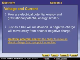
Voltage The voltage across an element is the work (energy) required to move a unit positive charge from the ̶ terminal to the + terminal. The unit of voltage is the volt, V. A potential difference of 1 volt (V) exists between two points if 1 joul (J) of energy is exchanged in moving 1 coulomb (C) of charge between the two points. In general, the potential difference between two points is determined by: V = voltage (V) Q = coulombs (C) W = potential energy (J) FIGURE 1.9 Defining the unit of measurement for voltage. ET162 Circuit Analysis –Current and Voltage Boylestad 14
Ex. 1-4 Find the potential difference between two points in an electrical system if 60 J of energy are expended by a charge of 20 C between these two points. Ex. 1-5 Determine the energy expended moving a charge of 50 μC through a potential difference of 6 V. ET162 Circuit Analysis –Current and Voltage Boylestad 15
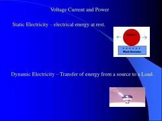
Fixed (dc) Supplies The terminology dc is an abbreviation for direct current, which encompasses the various electrical systems in which there is a unidirectional (“one direction”) flow of charge. DC Voltage Sources Dc voltage sources can be divided into three broad categories: (1)Batteries (chemical action), (2) generators (electro-mechanical), and (3) power supplies (rectification). FIGURE 1.11 Terminal characteristics: (a) ideal voltage source; (b) ideal current source. FIGURE 1.10 Symbol for a dc voltage source. ET162 Circuit Analysis –Current and Voltage Boylestad 16
Current The electrical effects caused by charges in motion depend on the rate of charge flow. The rate of charge flow is known as the electrical current. With no external forces applied, the net flow of charge in a conductor in any direction is zero. FIGURE 1.12 Basic electrical circuit. ET162 Circuit Analysis –Current and Voltage Boylestad 17
If electrons (1 coulomb) pass through the imaginary plane in Fig. 2.9 in 1 second, the flow of charge, or current, is said to be 1 ampere (A). The current in amperes can now be calculated using the following equation: I = amperes (A) Q = coulombs (C) t = seconds (s) ET162 Circuit Analysis –Current and Voltage Boylestad 18
Ex. 1-6 The charge flowing through the imaginary surface of Fig. 1-12 is 0.16 C every 64 ms. Determine the current in ampere. Ex. 1-7 Determine the time required for 4 × 10¹⁶ electrons to pass through the imaginary surface of Fig. 1.12 if the current is 5 mA. ET162 Circuit Analysis –Current and Voltage Boylestad 19
Ammeters and Voltmeters It is important to be able to measure the current and voltage levels of an operating electrical system to check its operation, isolate malfunctions, and investigate effects. Ammeters are used to measure current levels while voltmeters are used to measure the potential difference between two points. FIGURE 1.13 Voltmeter and ammeter connection for an up-scale (+) reading. ET162 Circuit Analysis – Voltage and Current Boylestad 20