Download
1 / 26
260 likes | 412 Vues
NDCX-II Project Joe Kwan Project Manager Sept. 7, 2009 San Francisco US-Japan Workshop on Heavy Ion Fusion and High Energy Density Physics. Outline. Scientific Motivation for NDCX-II NDCX-II Physics Design Accelerator System: —Physics —Mechanical —Electrical Project Management

E N D
NDCX-II Project Joe KwanProject Manager Sept. 7, 2009San Francisco US-Japan Workshop onHeavy Ion Fusion and High Energy Density Physics
Outline • Scientific Motivation for NDCX-II • NDCX-II Physics Design • Accelerator System: —Physics —Mechanical —Electrical • Project Management • Summary
NDCX-II is ideally suited for heating foils to WDM regime LITHIUM ION BEAM BUNCH Final Beam Energy:> 3 MeV Final Spot diameter : ~ 1 mm Final bunch length : ~ 1 cm or ~ 1 ns Total Charge Delivered: > 20 nC mm foil orfoam TARGET Exiting beam available for dE/dx measurement 30 J/cm2 isochoric heating will raise aluminum temperature to ~ 1 eV
Technical Approaches • Use an induction accelerator to compress beam pulse quickly down to ~ 1 ns • Neutralized drift compression and final focus of an intense beam to a small spot • Reuse the ATA induction cells and utilize an existing building to save cost and construction time • Design a flexible machine to enable future HIF driver development • Use the lighter Li ions to optimize the performance of NDCX-II (as limited by cost and schedule) • Consider solenoids, electric quads and magnetic quads beam focusing and chose the one that is most effective
NDCX-II generates short pulses needed for isochoric heating > 3 MV, 20 nC Ion source~ 500ns accel-decelinjector provides pre-bunching Induction Linacprovides custom waveforms for rapid beam compression Neutralized drift compression and final focus Target foil • Key design parameters: • ~100 mA Li+ Ion source at > 1 mA/cm2. • Induction cell voltage average gradient 0.25 MV/m (peak 0.75 MV/m). • Build new 2T solenoids for beam transport. • Use existing 8T solenoid for final focus.
The induction linac is ideal for compressinghigh-current short-pulse beams • An induction linac works like a series of transformers using the beam as a “single-turn” secondary. • Volt-seconds in the core material limits the pulse length. • Applied voltage waveforms determine the acceleration schedule. Advanced Test Accelerator (ATA) DARHT-II DARHT-II
The NDCX-II baseline physics design effectively combines acceleration and compression • Run 1-D Particle-in-cell (PIC) code with a few hundred particles for design synthesis: • Models gaps as extended fringing field. • Self-field model guided by results from Warp runs. • Can use realistic acceleration waveforms. • Also include centroid tracking for study of misalignment effects. • Run comprehensive PIC code “Warp” for detailed design: • 3-D and axisymmetric (r,z) models. • Electrostatic space charge and accelerating gap fields included. • Time-dependent space-charge-limited emission. • Extensively benchmarked against experiments and analytic cases. See A. Friedman’s paper in this conference
NDCX-II beam experiments are relevant to HIF drivers • HIF driver-like compression of non-neutral and neutralized beams. • Explore limits on velocity tilt. • Employs space charge to remove velocity tilt. • Longitudinal beam control. • Chromatic aberration in final focus. • Possible to add a quadrupole transport section at the end. • Beam diagnostic development. Beam Compression in NDCX-II Pulse length (m) Center of mass z position
Evolution of the phase space and the line charge density peak compression entering linac mid-compression Ek (MeV) (C/m) z (m) exiting expanding at focus
A simple passive circuit can generate a wide variety of waveforms Waveforms needed for NDCX-II charged line ATA “compensation box” induction cell & accelerating gap impedance
NDCX-II will coexist with NDCX-I in LBNL’s Building 58 high bay
NDCX-II Conceptual Design Layout water-filled Blumleins 100mA, 500ns Li+ ion injector final focus and target chamber Induction cells neutralized drift compression region with plasma sources
Schematic of the Induction Cell HV FEED INSULATOR OIL VACUUM 1.5 – 3 T PULSED SOLENOID (ATA used a lower field dc one) BEAM 5.5” FERRITE TORROID(70 ns, 250 kV) 11.0”
NDCX-II ion source and target are similar to NDCX-I Injector • Text goes here Targetchamber 102 kV pulsed source 68 kV DCextraction electrode -170 kV DCaccel electrode NDCX-I NDCX-II Ion mass K (A=39) Li (A=7) Ion energy 350 keV > 3 MeV Focal spot diameter ~ 2 mm 1 mm Pulse duration 2 – 4 ns 1 ns Peak current ~ 2 A ~ 30 A
NDCX-II Beam Neutralization is Based on NDCX-I Neutralization Experience Ferroelectric Plasma Source Developed by PPPL Cathodic-Arc Plasma Source 8/17/2014 1
NDCX-II will modify and change configuration of ATA hardware • Pulsed 3T solenoid instead of 5kG DC solenoid • Effect of the solenoid return flux on the available core volt-seconds is being studied on the test stand • Mismatched load for Blumlein to generate compression waveforms • Derating the Blumlein output voltage from 250kV to 200kV • Higher safety margin on insulators to protect from possible high amplitude reflections which are a result of impedance mismatching • Offsets the potential partial saturation of ferrite from solenoid return flux • DC charging of the switch chassis instead of the CRC system • Simpler and adequate for the much lower repetition rate
NDCX-II will modify and change configuration of ATA hardware • Separate trigger system for each Blumlein instead of distributed Blumlein pulse for triggering many Blumleins • Beam transit time is too long for cable delays • System jitter using a commercial 100kV trigger generator is being studied on the test stand • One transmission line between Blumlein and cell • Obvious mismatch, but load is not matched either • Step-up for nominal flat pulse • Simpler installation • Feed cell from alternating sides to cancel minor dipole effect • X and Y corrector for each solenoid • Effect of the saturating ferrite during the reset and main pulse on dipole strength is being studied on the test stand
NDCX-II Electrical Systems • Injector high voltage pulsers (2) and power supply (1) for beam extraction • Pulsed power systems (34) to produce the acceleration and compression waveforms at the induction cells • 10 spark gap switched lumped element or transmission line pulsers • 24 ATA Blumleins with shaping elements at cells • High current pulsers (40) for the transport solenoids in the induction cells and intercells • Correction dipole pulsers (2 per solenoid) • Plasma source pulsers • Control system – 200 power supplies • Timing and trigger system – 200 triggers • Data acquisition system – 300 diagnostics • Interlock system – 100 status monitors
Technical Risk Areas were Identified • Ion source—Li+ current density of 1 mA/cm2 has been demonstrated and has a matched beam solution. • The injector still needs to be designed to handle the heat problem. • Custom voltage waveforms for ion acceleration—sensitivity study and test data are underway. • Solenoid magnet alignment—use state of the art mechanical alignment technique, and provide beam steering correction using dipole coils. • Shielding of the ferrite core and beam diagnostics from the pulsed solenoid field.
The NDCX-II Test Stand is operational and testing the performance of various hardware components Charging transformer Spark Gap Blumlein Oil-filled transmission line Thyratron switch chassis Shaping network Charging supplies and trigger generators Cell
Critical Path Analysis Slide 24
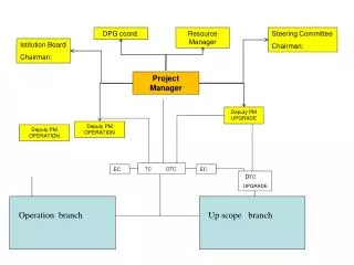
NDCX-II Project Team DOE OFESDave Goodwin Slide 25
Conclusions • NDCX-II will be a unique ion-driven user facility for warm dense matter and IFE target physics studies. • The machine will also allow beam dynamic experiments to study high-current drivers. • The baseline physics design makes optimal use of the ATA accelerator components through rapid beam compression and acceleration. • The project is $11M. It runs from July 2009 to March 2012. • NDCX-II is a prerequisite for the Integrated Beam–High Energy Density Physics Experiment in the 2007 DOE Office of Science Strategic Plan. • With NIF starting operation, now is the time to ramp up effort toward inertial fusion & fusion/fission hybrids.