Sand Sampling Apparatus
170 likes | 318 Vues
Sand Sampling Apparatus. Eglin Air Force Base Gina Teofilak Richard Klimas Dan Mortensen Ruben De Sousa. Overview. Introduction Current Design Maintenance and Safety Design Specifications Motion Control Motion Control Components Obstacles

Sand Sampling Apparatus
E N D
Presentation Transcript
Sand Sampling Apparatus Eglin Air Force Base Gina Teofilak Richard Klimas Dan Mortensen Ruben De Sousa
Overview • Introduction • Current Design • Maintenance and Safety • Design Specifications • Motion Control • Motion Control Components • Obstacles • Cost Analysis • Future Plans
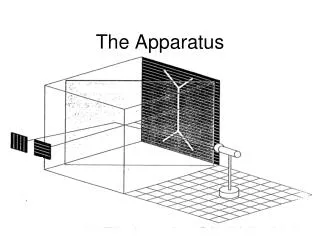
Introduction introduction Projectile Fractured sand Target shot line 3
Experimental Changes Eglin Visit 10/31/2008 Newly added forklift straddles 4
Current Design Current Design • Uses 2 linear motion actuators for Y and Z motion • ¾ inch ACME threaded rod • Designed to be a lead screw • Each will have an aluminum extrusion frame • Y and Z are different sizes • ¼ inch aluminum rod stabilizers for support • motion to be attained from 2 DC motors • Z- actuator is mounted directly to the Y- actuator • Legs of Y- actuator mount to wheels to produce X motion y X z 5
Motion in the X-direction Current Design • Chain and sprocket motion • Wheels fit inside aluminum extrusion grooves • DC motor attached to sprocket • Chain is clamped to actuator • Clamp has teeth of same pitch as the chain • Chain mount is adjustable for chain • tension 6
Future Considerations for X Axis • Instead of wheels, an eight foot long steel rod is considered with linear bearings • Steel rod will make it safer for installation than wheel base • Prevents tipping when installing onto experiment • Wheels might tip • Steel rod is cheaper
Maintenance and Safety • Material are corrosive resistant • Threaded rod is hardened stainless steel • Will not corrode based on interaction with other materials used • Experiment is only ran one time a month • When not used it will be stored in indoor atmosphere • To keep sand out of moving parts: • Bearings with brush guards will used • Plastic accordion style rod boots will cover the lead screws • Plastic guards will be mounted to keep sand out of x- actuator tracks • Lubrication is not required • Bearings are shielded • ACME lead screw does not require lubrication • Safety: • Chain guard • Safety stickers • By all moving parts and electrical components
Size: Length 96” Width 27” Height 24” • Weight: Mechanism 70 lbs. Vacuum 20 lbs. Electronics 5 lbs. • Vacuum Power: 6.5 Hp peak Volume: 20 gallons (supplied by Eglin) • Mechanism Speed: 2 in/sec Design Specifications
Motion Control • Motion control • 3 DC motors/ controllers • microprocessor • encoders/ switches • Y axis motion • threaded rod • aluminum rods for support • Z axis motion • threaded rod • vacuum tube rigidly attached • Control Sequence • z axis ½”-1” • y axis 24” • x axis 4” y X z 10
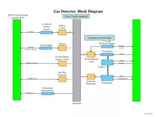
X Direction Movement Motor Controller Encoder Motor Z Direction Movement Motor Controller Encoder Wall Socket Power Supply Microprocessor Motor Y Direction Movement Motor Controller Switches Motor Motion Control Schematic • Control System Schematic • DC Power supply • Microprocessor stores code • Motor Controllers • Distances components • Motors • Geared motors • Required Torque
Encoders Switches Motion Control Components Why use different distance components? • Encoders • Convert rotations of shaft to code • Precise measurement of distance • Can be used to input exact position • Switches • Simple short circuit switches • Easier to program • Cheaper Encoder
Motion Control Obstacles • Make Screens • They are a problem • Break and Deform • Slightly unequally spaced • Removed for simplicity • Suggested from the sponsor • Projectile Entry Tube • Adds safety to the experiment • Cannot be removed • Mechanism is designed to avoid
Cost Analysis • Shipping • Machine Shop • Testing Facilities • Possible testing table • Current design is more expensive than using the rod • Material Cost • Donations
Future Plans • Purchase Parts • Machine and Assemble • Write the program • Test • Write Procedures • Make modifications • Conduct the Experiment • Meet the Class Deliverables December 2 – January 6 January 6 – April 24
REFERENCES • Cooper, William “Bill”, MSgt Wes Schuler, AFRL/RW • Munitions Directorate • Air Force Research Laboratory • Mortensen, Charles, Owner, Dynatech Associates • Dr. Chiang Shih, FAMU-FSU College of Engineering, Mechanical • Dr. Daudi Waryoba, FAMU-FSU College of Engineering, Mechanical Cost References Carbon Stick tape http://www.2spi.com/catalog/spec_prep/cond_adhes-discs.shtml Aluminum Extrusion Dynatech Associates McMASTER-CARR http://www.mcmaster.com/ 16