Essential Networking Commands for Windows: Understanding IP, MAC, and DNS Management
This presentation covers crucial network commands used in Windows for network configuration and troubleshooting. It includes practical demonstrations of commands such as Getmac for retrieving MAC addresses, Ipconfig for displaying IP configurations, Nslookup for DNS lookups, and Netstat for active connections. Each command is detailed with examples, providing a solid basis for troubleshooting network issues and managing TCP/IP configurations effectively. Perfect for students and professionals wanting to enhance their networking skills.

Essential Networking Commands for Windows: Understanding IP, MAC, and DNS Management
E N D
Presentation Transcript
Lecture 14 Computer Networking: A Top Down Approach 6th edition Jim Kurose, Keith RossAddison-WesleyMarch 2012 CS3516: These slides are generated from those made available by the authors of our text. Introduction
Get MAC Address (Getmac.exe) Discovers the Media Access Control (MAC) address and lists associated network protocols for all network cards in a computer, either locally or across a network. C:\Users\jb>getmac Physical Address Transport Name ============ ============================= 60-36-DD-AA-13-69 Media disconnected 60-36-DD-AA-13-65 \Device\Tcpip_{437F350E-DFD7-4A86-B063-0B9650BD4404} 60-36-DD-AA-13-66 Media disconnected 60-36-DD-AA-13-66 Media disconnected B8-CA-3A-DC-C6-2B Media disconnected 08-00-27-00-E4-38 \Device\Tcpip_{F551D578-DC71-4760-B91C-B349EAE4238F} Useful Commands Network Layer
IP Configuration Utility (Ipconfig.exe) Displays all current (TCP/IP) network configurations. C:\Users\jb>ipconfig Windows IP Configuration Ethernet adapter Local Area Connection: Connection-specific DNS Suffix . : WPI.EDU Link-local IPv6 Address . . . . . : fe80::e591:74d4:a495:7998%16 IPv4 Address. . . . . . . . . . . : 130.215.28.36 Subnet Mask . . . . . . . . . . . : 255.255.248.0 Default Gateway . . . . . . . . . : 130.215.24.1 C:\Users\jb>ipconfig /? Prints command line options C:\Users\jb>ipconfig /displaydns gives dns info cached on node cs.wpi.edu ---------------------------------------- Record Name . . . . . : cs.wpi.edu Record Type . . . . . : 1 Time To Live . . . . : 73497 Data Length . . . . . : 4 Section . . . . . . . : Answer A (Host) Record . . . : 130.215.28.181 Useful Commands Network Layer
Name Server Lookup (Nslookup.exe) Displays information about Domain Name System records for specific IP addresses and/or host names so that you can troubleshoot DNS problems. C:\Users\jb>nslookup www.google.com Server: a.resolvers.level3.net this is the name of the default server Address: 4.2.2.1 Non-authoritative answer: Name: www.google.com Addresses: 2607:f8b0:4000:804::1011 74.125.227.179 74.125.227.180 74.125.227.176 74.125.227.177 74.125.227.178 Useful Commands Network Layer
Net services commands (Net.exe) Performs a broad range of network tasks. Type net with no parameters to see a full list of available command-line options. C:\Users\jb>net help The syntax of this command is: Commands available are: NET ACCOUNTS NET HELPMSG NET STATISTICS NET COMPUTER NET LOCALGROUP NET STOP NET CONFIG NET PAUSE NET TIME NET CONTINUE NET SESSION NET USE NET FILE NET SHARE NET USER NET GROUP NET START NET VIEW NET HELP NET HELP NAMES explains different types of names in NET HELP syntax lines. NET HELP SERVICES lists some of the services you can start. NET HELP SYNTAX explains how to read NET HELP syntax lines. NET HELP command | MORE displays Help one screen at a time. Useful Commands Network Layer
Netstat(Netstat.exe) Displays active TCP connections, ports on which the computer is listening, Ethernet statistics, the IP routing table, and IPv4/IPv6 statistics. C:\Users\jb>netstat Proto Local Address Foreign Address State TCP 127.0.0.1:1029 jb-laptop:5354 ESTABLISHED TCP 127.0.0.1:1036 jb-laptop:27015 ESTABLISHED TCP 127.0.0.1:1047 jb-laptop:19872 ESTABLISHED TCP 127.0.0.1:39055 jb-laptop:39054 ESTABLISHED TCP 172.17.168.138:2492 blugro5relay:2492 ESTABLISHED C:\Users\jb>netstat -s IPv4 Statistics Packets Received = 10158258 Received Header Errors = 2848 Received Address Errors = 2192434 Datagrams Forwarded = 0 Unknown Protocols Received = 170614 Received Packets Discarded = 4173788 Received Packets Delivered = 6692404 Useful Commands Network Layer
Network Command Shell (Netsh.exe) Displays or modifies the network configuration of a local or remote computer that is currently running. This command-line scripting utility has a huge number of options, which are fully detailed in Help. TCP/IP Route (Route.exe) Displays and modifies entries in the local IP routing table. C:\Users\jb>route print Interface List 13...60 36 ddaa 13 65 ......Intel(R) Centrino(R) Wireless-N 2230 12...60 36 ddaa 13 69 ......Bluetooth Device (Personal Area Network) 31...08 00 27 00 e4 38 ......VirtualBox Host-Only Ethernet Adapter IPv4 Route Table Network Destination Netmask Gateway Interface Metric 0.0.0.0 0.0.0.0 172.17.1.1 172.17.168.138 25 127.0.0.0 255.0.0.0 On-link 127.0.0.1 306 127.0.0.1 255.255.255.255 On-link 127.0.0.1 306 127.255.255.255 255.255.255.255 On-link 127.0.0.1 306 169.254.0.0 255.255.0.0 On-link 169.254.40.182 276 169.254.40.182 255.255.255.255 On-link 169.254.40.182 276 169.254.255.255 255.255.255.255 On-link 169.254.40.182 276 172.17.0.0 255.255.0.0 On-link 172.17.168.138 281 172.17.168.138 255.255.255.255 On-link 172.17.168.138 281 172.17.255.255 255.255.255.255 On-link 172.17.168.138 281 224.0.0.0 240.0.0.0 On-link 169.254.40.182 276 Useful Commands Network Layer
(Arp.exe) Displays current ARP entries by interrogating the current protocol data. If inet_addr is specified, the IP and Physical addresses for only the specified computer are displayed. If more than one network interface uses ARP, entries for each ARP table are displayed. C:\Users\jb>arp -a Interface: 130.215.28.36 --- 0x10 Internet Address Physical Address Type 130.215.24.1 00-00-5e-00-01-01 dynamic 130.215.24.2 00-23-9c-94-97-f0 dynamic 130.215.27.252 f0-1f-af-2f-e1-27 dynamic 130.215.28.63 00-16-3e-c5-01-25 dynamic 130.215.29.165 00-24-e8-32-32-1d dynamic 130.215.31.255 ff-ff-ff-ff-ff-ff static Useful Commands Network Layer
5.4 LANs addressing, ARP Ethernet switches VLANS 5.5 link virtualization: MPLS 5.6 data center networking 5.7 a day in the life of a web request Lecture 14: outline Link Layer
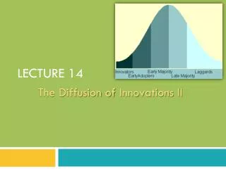
Ethernet “dominant” wired LAN technology: • cheap $20 for NIC • first widely used LAN technology • simpler, cheaper than token LANs and ATM • kept up with speed race: 10 Mbps – 10 Gbps Metcalfe’s Ethernet sketch Link Layer
Ethernet: physical topology • bus: popular through mid 90s • all nodes in same collision domain (can collide with each other) • star: prevails today • active switchin center • each “spoke” runs a (separate) Ethernet protocol (nodes do not collide with each other) switch star bus: coaxial cable Link Layer
Ethernet frame structure sending adapter encapsulates IP datagram (or other network layer protocol packet) in Ethernet frame preamble: • 7 bytes with pattern 10101010 followed by one byte with pattern 10101011 • used to synchronize receiver, sender clock rates type dest. address source address data (payload) CRC preamble Link Layer
Ethernet frame structure (more) • addresses: 6 byte source, destination MAC addresses • if adapter receives frame with matching destination address, or with broadcast address (e.g. ARP packet), it passes data in frame to network layer protocol • otherwise, adapter discards frame • type: indicates higher layer protocol (mostly IP but others possible, e.g., Novell IPX, AppleTalk) • CRC: cyclic redundancy check at receiver • error detected: frame is dropped type dest. address source address data (payload) CRC preamble Link Layer
Ethernet: unreliable, connectionless • connectionless: no handshaking between sending and receiving NICs • unreliable: receiving NIC doesn’t send acks or nacks to sending NIC • data in dropped frames recovered only if initial sender uses higher layer rdt (e.g., TCP), otherwise dropped data lost • Ethernet’s MAC protocol: unslottedCSMA/CD wth binary backoff Link Layer
802.X • 802.1 LAN Management • 802.2 Defines Logical Link Control – the upper part of the Data Link Layer • 802.3 Ethernet (wired) • 802.4 Token Bus • 802.5 Token Ring • 802.6 MAN Definition • 802.11 Ethernet (Wireless) Link Layer
application transport network link physical fiber physical layer copper (twister pair) physical layer 802.3 Ethernet standards: link & physical layers • manydifferent Ethernet standards • common MAC protocol and frame format • different speeds: 2 Mbps, 10 Mbps, 100 Mbps, 1Gbps, 10G bps • different physical layer media: fiber, cable MAC protocol and frame format 100BASE-T2 100BASE-FX 100BASE-TX 100BASE-BX 100BASE-SX 100BASE-T4 Link Layer
5.4 LANs addressing, ARP Ethernet switches VLANS 5.5 link virtualization: MPLS 5.6 data center networking 5.7 a day in the life of a web request Lecture 14: outline Link Layer
Ethernet switch • link-layer device: takes an active role • store, forward Ethernet frames • examine incoming frame’s MAC address, selectively forward frame to one-or-more outgoing links when frame is to be forwarded on segment, uses CSMA/CD to access segment • transparent • hosts are unaware of presence of switches • plug-and-play, self-learning • switches do not need to be configured Link Layer
Switch: multiple simultaneous transmissions • hosts have dedicated, direct connection to switch • switches buffer packets • Ethernet protocol used on each incoming link, but no collisions; full duplex • each link is its own collision domain • switching:A-to-A’ and B-to-B’ can transmit simultaneously, without collisions A B C’ 1 2 6 4 5 3 B’ C A’ switch with six interfaces (1,2,3,4,5,6) Link Layer
Switch forwarding table Q:how does switch know A’ reachable via interface 4, and B’ reachable via interface 5? A B C’ • A:each switch has a switch table,each entry: • (MAC address of host, interface to reach host, time stamp) • looks like a routing table! 1 2 6 4 5 3 B’ C Q:how are entries created, maintained in switch table? • something like a routing protocol? A’ switch with six interfaces (1,2,3,4,5,6) Link Layer
Source: A Dest: A’ MAC addr interface TTL 60 1 A A A’ Switch: self-learning • switchlearnswhich hosts can be reached through which interfaces • when frame received, switch “learns” location of sender: incoming LAN segment • records sender/location pair in switch table A B C’ 1 2 6 4 5 3 B’ C A’ Switch table (initially empty) Link Layer
Switch: frame filtering/forwarding when frame received at switch: 1. record incoming link, MAC address of sending host 2. index switch table using MAC destination address 3. ifentry found for destinationthen { ifdestination on segment from which frame arrivedthen drop frame else forward frame on interface indicated by entry } elseflood /* forward on all interfaces except arriving interface */ Link Layer
Source: A Dest: A’ A’ A MAC addr interface TTL 60 60 1 4 A A’ A A’ A A’ A A’ A A’ A A’ A A’ Self-learning, forwarding: example • frame destination, A’, location unknown: A flood B • destination A location known: C’ selectively send on just one link 1 2 6 4 5 3 B’ C A’ switch table (initially empty) Link Layer
Interconnecting switches • switches can be connected together S4 S1 S3 S2 A F I D C B H G E • Q: sending from A to G - how does S1 know to forward frame destined to F via S4 and S3? • A:self learning! (works exactly the same as in single-switch case!) Link Layer
Self-learning multi-switch example Suppose C sends frame to I, I responds to C S4 S1 S3 S2 A F I D C B H G E • Q:show switch tables and packet forwarding in S1, S2, S3, S4 Link Layer
Institutional network mail server to external network web server router IP subnet Link Layer
network link physical link physical datagram datagram frame frame frame Switches vs. routers application transport network link physical both are store-and-forward: • routers: network-layer devices (examine network-layer headers) • switches: link-layer devices (examine link-layer headers) both have forwarding tables: • routers: compute tables using routing algorithms, IP addresses • switches: learn forwarding table using flooding, learning, MAC addresses switch application transport network link physical Link Layer
5.4LANs addressing, ARP Ethernet Switches VLANS 5.6 data center networking 5.7 a day in the life of a web request Lecture 14: outline Link Layer
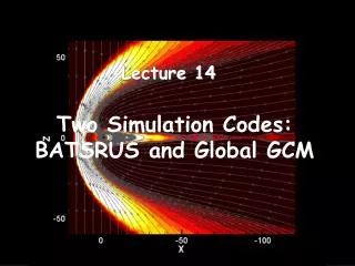
Data center networks • 10’s to 100’s of thousands of hosts, often closely coupled, in close proximity: • e-business (e.g. Amazon) • content-servers (e.g., YouTube, Akamai, Apple, Microsoft) • search engines, data mining (e.g., Google) • challenges: • multiple applications, each serving massive numbers of clients • managing/balancing load, avoiding processing, networking, data bottlenecks Inside a 40-ft Microsoft container, Chicago data center Link Layer
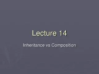
Data center networks • load balancer: application-layer routing • receives external client requests • directs workload within data center • returns results to external client (hiding data center internals from client) Internet Border router Load balancer Load balancer Access router Tier-1 switches B A C Tier-2 switches TOR switches Server racks 7 6 5 4 8 3 2 1 Link Layer
Data center networks • rich interconnection among switches, racks: • increased throughput between racks (multiple routing paths possible) • increased reliability via redundancy Tier-1 switches Tier-2 switches TOR switches Server racks 7 6 5 4 8 3 2 1
5.4LANs addressing, ARP Ethernet switches VLANS 5.5 link virtualization: MPLS 5.6 data center networking 5.7 a day in the life of a web request Lecture 14: outline Link Layer
Synthesis: a day in the life of a web request • journey down protocol stack complete! • application, transport, network, link • putting-it-all-together: synthesis! • goal:identify, review, understand protocols (at all layers) involved in seemingly simple scenario: requesting www page • scenario:student attaches laptop to campus network, requests/receives www.google.com Link Layer
browser A day in the life: scenario DNS server Comcast network 68.80.0.0/13 school network 68.80.2.0/24 web page web server Google’s network 64.233.160.0/19 64.233.169.105 Link Layer
DHCP UDP IP Eth Phy DHCP UDP IP Eth Phy DHCP DHCP DHCP DHCP DHCP DHCP DHCP DHCP DHCP DHCP A day in the life… connecting to the Internet • connecting laptop needs to get its own IP address, addr of first-hop router, addr of DNS server: use DHCP • DHCP request encapsulatedin UDP, encapsulated in IP, encapsulated in 802.3Ethernet router (runs DHCP) • Ethernet frame broadcast (dest: FFFFFFFFFFFF) on LAN, received at router running DHCPserver • Ethernet demuxed to IP demuxed, UDP demuxed to DHCP Link Layer
DHCP UDP IP Eth Phy DHCP UDP IP Eth Phy DHCP DHCP DHCP DHCP DHCP DHCP DHCP DHCP DHCP A day in the life… connecting to the Internet • DHCP server formulates DHCP ACKcontaining client’s IP address, IP address of first-hop router for client, name & IP address of DNS server • encapsulation at DHCP server, frame forwarded (switch learning) through LAN, demultiplexing at client router (runs DHCP) • DHCP client receives DHCP ACK reply Client now has IP address, knows name & addr of DNS server, IP address of its first-hop router Link Layer
ARP ARP Eth Phy ARP query ARP reply DNS UDP IP Eth Phy DNS DNS DNS A day in the life… ARP (before DNS, before HTTP) • before sending HTTPrequest, need IP address of www.google.com: DNS • DNS query created, encapsulated in UDP, encapsulated in IP, encapsulated in Eth. To send frame to router, need MAC address of router interface: ARP • ARP querybroadcast, received by router, which replies with ARP replygiving MAC address of router interface router (runs DHCP) • client now knows MAC address of first hop router, so can now send frame containing DNS query Link Layer
DNS UDP IP Eth Phy DNS UDP IP Eth Phy DNS DNS DNS DNS DNS DNS DNS DNS DNS A day in the life… using DNS DNS server Comcast network 68.80.0.0/13 • IP datagram forwarded from campus network into comcast network, routed (tables created by RIP, OSPF, IS-ISand/or BGP routing protocols) to DNS server router (runs DHCP) • IP datagram containing DNS query forwarded via LAN switch from client to 1st hop router • demux’ed to DNS server • DNS server replies to client with IP address of www.google.com Link Layer
SYN SYN SYN SYN SYN SYN SYN HTTP TCP IP Eth Phy TCP IP Eth Phy HTTP SYNACK SYNACK SYNACK SYNACK SYNACK SYNACK SYNACK A day in the life…TCP connection carrying HTTP • to send HTTP request, client first opens TCP socket to web server router (runs DHCP) • TCP SYN segment(step 1 in 3-way handshake) inter-domain routed to web server • web server responds with TCP SYNACK(step 2 in 3-way handshake) web server 64.233.169.105 • TCP connection established! Link Layer
HTTP TCP IP Eth Phy HTTP TCP IP Eth Phy HTTP HTTP HTTP HTTP HTTP HTTP HTTP HTTP HTTP HTTP HTTP HTTP HTTP HTTP A day in the life… HTTP request/reply • web page finally (!!!)displayed • HTTP requestsent into TCP socket • IP datagram containing HTTP request routed to www.google.com router (runs DHCP) • web server responds with HTTP reply(containing web page) web server • IP datagram containing HTTP reply routed back to client 64.233.169.105 Link Layer