LBNL Leo Greiner , Eric Anderssen ,
240 likes | 399 Vues
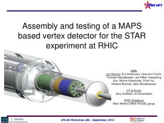
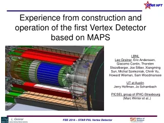
The STAR PXL read-out system. LBNL Leo Greiner , Eric Anderssen , Thorsten Stezelberger , Joe Silber, Xiangming Sun, Michal Szelezniak , Chinh Vu, Howard Wieman UTA Jerry Hoffman, Jo Schambach IPHC Strasburg Marc Winter CMOS group. Talk Outline.

LBNL Leo Greiner , Eric Anderssen ,
E N D
Presentation Transcript
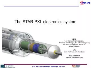
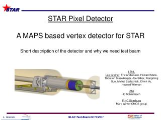
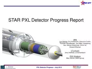
The STAR PXL read-out system LBNL Leo Greiner, Eric Anderssen, Thorsten Stezelberger, Joe Silber, Xiangming Sun, Michal Szelezniak, Chinh Vu, Howard Wieman UTA Jerry Hoffman, Jo Schambach IPHC Strasburg Marc Winter CMOS group
Talk Outline • Detector description and basic units • RDO constraints and requirements • Hardware architecture of RDO system • Integrated structure of system with testing needs • Firmware design • Prototyping and system testing • Production system and status • Summary
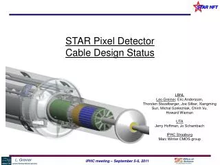
Aluminum conductor Ladder Flex Cable PXL Detector Mechanical Design Mechanical support with kinematic mounts (insertion side) carbon fiber sector tubes (~ 200µm thick) Insertion from one side 2 layers 5 sectors / half (10 sectors total) 4 ladders/sector Ladder with 10 MAPS sensors (~ 2×2 cm each) 20 cm
RDO System Considerations RDO is driven by several considerations • Sensor output – we have some control. RDO places some requirements on the sensor design. Pattern output registers for Xilinx IOdelay, differential outputs, production testability, etc. • STAR DAQ, Trigger, slow controls, etc. – we have less control. • Physical layout of the detector in STAR. • RDO system is an evolution based on final needs, sensor development plan and testing needs.
PXL RDO System Requirements • Interface to the sensors for readout and control. (160 MHz LVDS data, JTAG control, Clock, START, Temp) • Triggered detector system fitting into existing STAR infrastructure (Trigger, DAQ, etc.) • Deliver full frame events to STAR DAQ for event building at approximately the same rate as the TPC (1 kHz for DAQ1000) using the ALICE and now STAR standard DDL fiber interface. • Have live time characteristics such that the Pixel detector is live whenever the TPC is live. (PXL adds ≤ 5% additional dead time) • Reduce the total data rate of the detector to a manageable level (< TPC rate of ~1MB / event). • Reliable, cost effective, etc. • Provide additional functionality for sensor testing including production probe testing (ADCs, USB, SRAM for frame mode data taking)
Physical Constraints Magnetic field + high rad sensors Main RDO board ≤ 8m Ladder cable STAR DAQ RDO PC DDL Fiber optic Connection ~50 m Built events To HLT and storage
Sensor generation and RDO attributes CDS Data sparsification readout to DAQ Pixel Sensors Disc. 3 generation program with highly coupled sensor and readout development Complementary detector readout digital signals analog signals digital ADC CDS analog MimoSTAR sensors 4 ms integration time 1 2 Production Readout Phase-1 sensors 640 μs integration time 3 PXL production sensors (Ultimate) < 200 μs integration time Sensor and RDO Development Path
System Constraints • We need FPGA processing to do zero suppression (Phase-2) and event building. This necessitates moving the processing out of the high radiation area. (SEU) • The constraint of locating the event fast pre-processing hardware ~8m from the sensors (in a lower radiation area) requires a driver/mass termination board located between the sensors and the processing hardware. This is required for mechanical and signal integrity reasons. • This provides additional benefit that the main part of the electronics is in an area that is serviceable during a cave access. • This leads to a 3 main component architecture.
PXL Detector Basic Unit (RDO) 6 m (24 AWG TP) 2 m (42 AWG TP) Mass Termination Board + latch-up protected power daughter-card Clk, config, data Clk, config, data, power RDO motherboard w/ Xilinx FPGA RDO PC with DDL link to RDO board 100 m (fiber optic) PXL built events • Highly parallel system • 4 ladders per sector • 1 Mass Termination Board (MTB) per sector • 1 sector per RDO board • 10 RDO boards in the PXL system
PXL RDO Architecture (1 sector) i/o USB ADC SIU FPGA DAQ RDO PCs SRAM Power Supplies Control PCs Trigger Ladder x 4 RDO board x 1 fiber Unified Development Platform Sensor testing Probe testing LU prot. power Black – cfg, ctl, clk. path Blue – data path Red – power / gnd path Green – testing path MTB x 1
Functional Data Path – Phase-1 After power-on and configuration, all sensors are run continuously and data is streamed through the RDO path to the RDO motherboards Highly Parallel FPGA based RDO system • 40 sensor outputs/ladder • 1 sector / RDO board • Each received trigger enables an event buffer for one frame. • The system is dead-time free up to the hardware buffering limit. 160 independent sensor data chains
Functional Data Path – PXL Sensor After power-on and configuration, all sensors are run continuously and data is streamed through the RDO path to the RDO motherboards Highly Parallel FPGA based RDO system • 20 sensor outputs/ladder • 1 sector / RDO board Same hardware with reconfigured firmware Each received trigger enables an event buffer for one frame. Triggered event boundaries are determined by data order.
analog signal LVDS signal JTAG I2C ADC ADC IO delay System control Frame fifo SRAM fifo Event machine info machine DDL USB Firmware Architecture Modules Phase-2 and Ultimate sensors + testing Temperature DAQ Status monitor
Simple Data Rates PXL System (Production Sensor) • Data rate to storage = 199 MB/sec (1kHz trigger) • 199 kB / event
Prototype Ladder Test with Prototype RDO Architecture verified with LVDS data path test using prototype RDO and fan out based ladder equivalent. Measured BER ~ 10-14 6 m (24 AWG TP) 2 m (42 AWG TP) Clk, config, data Clk, cfg, data, pwr Mass Termination Board + latch-up protected power daughter-card Infrastructure Test Board 100 m (fiber optic) PXL built events RDO PC with DDL link to RDO board RDO motherboard Prototypew/ Xilinx Virtex-5 FPGA Equivalent to a 1 ladder full system test
System Testing Results • Data path and architecture are validated. • Interfaces to STAR slow controls, Trigger and DAQ have been tested in a beam test at STAR. • First prototypes have been used to read out ladder prototypes and characterize the operating envelope of sensors in this configuration (more on this in Michal Szelezniak’s talk). The working system is also used for individual sensor testing and characterization, Beam tests, LU and SEU testing, etc. • Prototype hardware, firmware and software are all working well. • This allows for the design of the production system.
Production System Design We will use the 9U VME physical standard for RDO motherboards. (Not the electrical standard) 1 standard VME crate with P1 backplane for STAR TCD distribution. Data from sectors arrives via cables plugging into the back of the RDO boards in the P2/P3 locations. STAR TCD • System consists of: • 10 double wide 9U VME RDO boards • 1 single wide 6U VME TCD board SIU SIU SIU SIU SIU SIU SIU SIU SIU SIU Daughter Card Daughter Card Daughter Card Daughter Card Daughter Card Daughter Card Daughter Card Daughter Card Daughter Card Daughter Card 356 M pixel readout in a single 9U VME crate USB USB USB USB USB USB USB USB USB USB JTAG JTAG JTAG JTAG JTAG JTAG JTAG JTAG JTAG JTAG Standard 21 slot 9U VME crate
Production Prototype RDO board SIU VME P1 Daughter Card USB Ladder Data Connectors (VHDCI) JTAG Xilinx Virtex-6 FPGA
Production Prototypes MTB, Cable • The prototype MTB works well and will undergo a re-spin to fit into the existing space in the insertion tube. • The TCD interface 6U VME board has been designed and is currently being fabricated. • The ladder cable is currently being designed based on information gained from the ITB testing. This should be complete in the next few months. • All components used in the MTB or ladder have been tested for SEU and Latch-up.
PXL RDO Summary • The RDO for the STAR HFT PXL system is the culmination 3 generations of sensors and RDO over many years of development. • We have a design that meets the requirements and has been prototyped successfully. • Our design is integrated such that we will use production RDO boards with daughter cards to perform all sensor, probe testing and construction production testing. • The production prototypes are designed, mostly constructed and under test. • The RDO for the full PXL detector will fit into 1 9U VME crate. • We will install a prototype detector using the pre-production RDO in late 2012.
RDO System Design – Physical Layout Sensors / Ladders / Sectors (interaction point) RDO Boards 1-2 m Low mass twisted pair LU Protected Regulators, Mass cable termination Platform 30 m Power Supplies 6 m - twisted pair 30 m 100 m - Fiber optic Control PCs 30 m DAQ Room DAQ PCs (Low Rad Area)
PXL Detector Basic Unit (RDO) 6 m (24 AWG TP) 2 m (42 AWG TP) Clk, config, data Clk, config, data, power Mass Termination Board + latch-up protected power daughter-card 100 m (fiber optic) PXL built events RDO PC with DDL link to RDO board • Highly parallel system • 4 ladders per sector • 1 Mass Termination Board (MTB) per sector • 1 sector per RDO board • 10 RDO boards in the PXL system RDO motherboard w/ Xilinx FPGA
Production RDO Board Concept PXL RDO is 1 x 6U and 10 x 9U RDO board layout TCD SIU VME P1 VME P1 Expansion board TCD 6U VME Board VHDCI X 4 JTAG x10 USB