Download
1 / 15
150 likes | 288 Vues
STAR Pixel Detector A MAPS based vertex detector for STAR Short description of the detector and why we need test beam. LBNL Leo Greiner , Eric Anderssen, Howard Matis, Thorsten Stezelberger, Joe Silber, Xiangming Sun, Michal Szelezniak, Chinh Vu, Howard Wieman UTA Jo Schambach

E N D
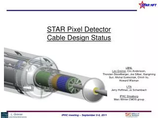
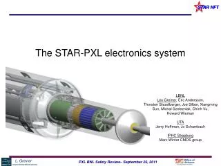
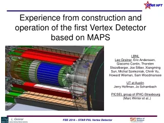
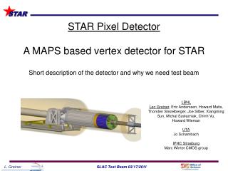
STAR Pixel DetectorA MAPS based vertex detector for STAR Short description of the detector and why we need test beam LBNL Leo Greiner, Eric Anderssen, Howard Matis, Thorsten Stezelberger, Joe Silber, Xiangming Sun, Michal Szelezniak, Chinh Vu, Howard Wieman UTA Jo Schambach IPHC Strasburg Marc Winter CMOS group
Vertex Detector Motivation • Direct Topological reconstruction of Charm • Detect charm decays with small c, including D0 K Method: Resolve displaced vertices (100-150 microns)
Inner Detector Upgrades TPC – Time Projection Chamber (main tracking detector in STAR) HFT – Heavy Flavor Tracker • SSD – Silicon Strip Detector • r = 22 cm • IST – Inner Silicon Tracker • r = 14 cm • PXL – Pixel Detector • r = 2.5, 8 cm We track inward from the TPC with graded resolution: ~1mm ~300µm ~250µm <30µm vertex TPC SSD IST PXL
Aluminum conductor Ladder Flex Cable PXL Detector Mechanical Design Cabling and cooling infrastructure Mechanical support with kinematic mounts (insertion side) carbon fiber sector tubes (~ 200um thick) Insertion from one side 2 layers 5 sectors / half (10 sectors total) 4 ladders/sector Ladder with 10 MAPS sensors (~ 2×2 cm each) 20 cm
Detector Characteristics 356 M pixels on ~0.16 m2 of Silicon
Test Beam use MAPS sensor characteristics: Column parallel RDO with in-chip CDS, discriminators and zero-suppression. 2011 • Characterize pre-production prototype sensors in a beam telescope configuration to check efficiency and resolution as a function of bias and discriminator settings for MIPS. 2012 • Prototype sector and detector tests. Test tracking with MIPs through 4 layers of detector. Track stability with cooling air flowing. 2013 • Production sector and detector tests. As above.
Beam Test Packages Beam Telescope Sector and detector apparatus with air cooling housing and blower
PXL Detector Basic Unit (RDO) 6 m (24 AWG TP) 2 m (42 AWG TP) Clk, config, data Clk, config, data, power Mass Termination Board + latch-up protected power daughter-card 100 m (fiber optic) PXL built events RDO PC with DDL link to RDO board • Highly parallel system • 4 ladders per sector • 1 Mass Termination Board (MTB) per sector • 1 sector per RDO board • 10 RDO boards in the PXL system RDO motherboard w/ Xilinx Virtex-5 FPGA
Monolithic Active Pixel Sensors MAPS pixel cross-section (not to scale) • Standard commercial CMOS technology • Room temperature operation • Sensor and signal processing are integrated in the same silicon wafer • Signal is created in the low-doped epitaxial layer (typically ~10-15 μm) → MIP signal is limited to <1000 electrons • Charge collection is mainly through thermal diffusion (~100 ns), reflective boundaries at p-well and substrate → cluster size is about ~10 pixels (20-30 μm pitch) • 100% fill-factor • Fast readout • Proven thinning to 50 micron
RDO System Design – Physical Layout Sensors / Ladders / Sectors (interaction point) RDO Boards 1-2 m Low mass twisted pair LU Protected Regulators, Mass cable termination Platform 30 m Power Supplies 6 m - twisted pair 30 m 100 m - Fiber optic Control PCs 30 m DAQ Room DAQ PCs (Low Rad Area)
PXL RDO Architecture (1 sector) i/o USB ADC SIU FPGA DAQ RDO PCs SRAM Power Supplies Control PCs Trigger Ladder x 4 RDO board x 1 fiber Unified Development Platform Sensor testing Probe testing LU prot. power Black – cfg, ctl, clk. path Blue – data path Red – power / gnd path Green – testing path MTB x 1