CRANES
This document provides a comprehensive overview of turbine crane operations and maintenance at the Palo Verde Nuclear Generating Station. It includes a general system diagram of various safety and operational systems, detailed procedures for crane operation, including pre-job briefs, troubleshooting, and programming of Allen Bradley PLCs. Key topics cover ensuring workable environments, identifying critical steps in operations, and adherence to safety protocols. This guide equips plant electricians with the necessary knowledge and skills to maintain crane equipment effectively.

CRANES
E N D
Presentation Transcript
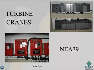
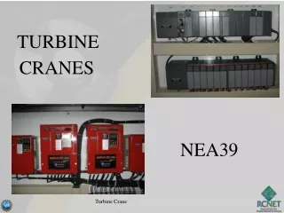
TURBINE CRANES NEA39 Turbine Crane
PLANT STATUS! General System Diagram of Palo Verde Nuclear Generating Station Legend:: Safety Injection Systems Reactor Coolant System To Switchyard Containment Building Main Steam System Main Feedwater System Main Condensate System CONTAINMENT SPRAY Circulating Water System Transformer Turbine Building Auxiliary Feedwater System Cooling Tower and Fans Safety Injection Tank Moisture Separator Reheaters MSSVs ADVs 8 8 8 Steam Generator Auxiliary Building MSIV Pressurizer MTSV Control Rods MSSS Shutdown Heat Exchanger HP LP LP LP Generator Bldg. Turbine Turbine Turbine Turbine Equipment Cooling MTCV Z From Auxiliary Feedwater Pumps Containment Spray Pump Turbine Bypass Valves Reactor Core Refueling Water Tank Condensate Pump Reactor Coolant Pump Main Condenser Low Pressure Safety Injection Pump (HP) Feedwater Heaters (LP) Feedwater Heaters Circulating Water Pump High Pressure Safety Injection Pump Feedwater Regulation Valve Main Feedwater Pump Polishing Demineralizers Containment Sump Turbine Crane PV Daily Status Report
Walk downs • Review instructions to ensure workable and adequate • Right Parts/materials/tools • Permits • Relevant Operating Experience Turbine Crane
Pre Job Briefs • Understand the Task • Critical Steps identified and OE used AND what actions are being taken in reference to these two areas • Two Minute Drills: • Hazards identified AND what are actions are you taking Turbine Crane
Procedure Use & Adherence • WO / procedure in hand & latest revision • Place keepers being used • Sign steps as you go • Follow & understand steps - STOP if can't or don't Turbine Crane
TURBINE CRANE • Terminal Objective Given references provided by the Instructor, the Plant Electrician will maintain Turbine Building Cranes as demonstrated by achieving a minimum of 80% on a written examination. Turbine Crane
. Multi Stud Tensioner
PRE-JOB BRIEF • Identify Critical Steps • Identify Error Precursors • Worst thing that can happen • Error prevention defenses to be used • Actions to assure proper configuration control Turbine Crane
TURBINE CRANE EO 1.6 Describe the Programming of the Allen Bradley SLC 5/04 Programmable Logic Controller
Software RSLogix 500 • RSLogix software is a Windows ladder logic programming tool for SLC500 processors. This software allows the user to: • Establish Communications with SLC 500 processors. • Display and monitor process data including FAULT Codes • Create and Modify new ladder logic • Configure your I/O modules Turbine Crane
Off-line Computer Operation ***Projects that reside on the hard disc of a computer*** Viewing Projects: • Projects are files that store all of the program logic and data for a single processor. • Example: Turbinecrane.rss Turbine Crane
Turbine.RSS Turbine Crane
Off-line Computer Operation Project Files: DataBase Files • Files that contain information which is not used by the processor and is typically stored in the computer memory only. • Examples: Custom Data Monitors, Trends etc… Turbine Crane
Turbine.RSS Turbine Crane
Off-line Computer Operation Processor Files: • Files that can be modified or monitored from the computer while they are being used by the PLC processor • Examples: Data Files, Program Files, Force Files. Turbine Crane
Turbine.RSS Turbine Crane
Off-line Computer Operation Viewing Ladder Logic: • To view ladder logic, you must first open the project you are interested in. • Next, you are to open the ladder file you are interested in i.e. LAD02 Turbine Crane
On-line Computer Operation ***Using the computer to view or work with a project that is loaded in a SLC 500 processor.*** Online: • The computer must be in continuous communication with the processor to allow the following actions can be performed: • Monitor or modify a project loaded in a processor • Monitor data while it is being collected • Modify data stored in a processor Turbine Crane
On-line Computer Operation ***Using the computer to view or work with a project that is loaded in a SLC 500 processor.*** Download: • Transfers a copy of a project from a computer to a processor. *****CAUTION***** Downloading will overwrite the program that is currently installed on the PLC. Turbine Crane
On-line Computer Operation ***Using the computer to view or work with a project that is loaded in a SLC 500 processor.*** Upload: • Transfers a copy of a project from a PLC Processor to the memory of a computer. • Because uploading allows the user to view the actual project that is on the processor, it is commonly used by maintenance personnel to troubleshoot and monitor a project. Turbine Crane
Connecting a Computer and Going On-line • RSLinx software must be loaded and enabled to allow communication between the computer and the processor. • A Communications Driver must be established to allow the software to communicate with the processor. • We will use Data Highway + (DH+) or RS-232 connection typically. • A cable will run from the computer to the Processor to establish the link. • Typically this will either be a RS-232 link or a PCMK (DH+) connection. • A USB to DH+ is also currently available. Turbine Crane
Modes of Operation There are 3 modes of control for the SLC500 processor and they allow different functions to occur. They are selected from a keyswitch on the front of the processor and allow functions to occur as follows: Turbine Crane
Processor Modes RUN – This is the mode you should find the PLC processor in. It allows the processor to perform its intended function and control the crane. • No programming can be performed in this mode. Turbine Crane
Processor Modes PROGRAM – (PROG) When this mode is selected, the operation of the crane will cease. Downloading / Uploading and modification of processor projects can occur. Turbine Crane
Processor Modes REMOTE – (REM) This mode is used to control a processor’s operating mode from the laptop connected to the processor. There are 3 separate modes of remote operation and they must be selected by the computer you have connected. Turbine Crane
Processor Modes REMOTE • Remote RUN – This will allow for crane operation while the computer is connected. • Remote PROGRAM – This is the same as the regular program mode. • Remote TEST – This mode will allow you to run a program from a computer but it will disable the outputs of the PLC. Turbine Crane
Memory Layout and System Addresses SLC 500 Software Address Characteristics: Example Address: • B 15 : 3 / 2 • B – indicates the File Type (B- Binary Bit) • 15 – indicates the File Number • 3 – indicates the Element number • 2 – indicates the Bit number Turbine Crane
Memory Layout and System Addresses SLC 500 Software Address Characteristics: Example Address: • T 14 : 2. PRE • T – indicates the File Type (T – Timer) • 14 – indicates the File Number • 2 – indicates the Element Number • PRE – would indicate a word address Turbine Crane
I : 3 / 10 • I –indicates the Module Type (I- Input) • 3 –indicates the Slot Number • 10–indicates the Terminal Number Memory Layout and System Addresses SLC 500 Hardware Address Characteristics: **Address for a hardware device (input or output) is directly determine by the module slot number and terminal to which the hardware device is wired. Example Address: • I : 3 / 10 • I – indicates the Module Type (I- Input) • 3 – indicates the Slot Number • 10– indicates the Terminal Number Turbine Crane
I : 3 / 10 • I –indicates the Module Type (I- Input) • 3 –indicates the Slot Number • 10–indicates the Terminal Number Memory Layout and System Addresses SLC 500 Hardware Address Characteristics: Example Address: • O : 5 / 3 • O – indicates the Module Type (O – Output) • 5 – indicates the Slot Number • 3 – indicates the Terminal Number Turbine Crane
F I N D THE H A R D W A R E A D D R E S S C O U N T E R M O D U L E # 4 Turbine Crane
I : 3 / 10 • I –indicates the Module Type (I- Input) • 3 –indicates the Slot Number • 10–indicates the Terminal Number Memory Layout and System Addresses SLC 500 Hardware Address Characteristics: Analog Example Address: O : 4 . 2 • O – Analog Module Type (O – Output) • 4 – indicates the slot number • . – indicates the Word Delimiter • 2 – indicates the analog channel number Turbine Crane
Hardware to Data Table Relationships Discrete modules • Each I/O module terminal point is represented by a bit in the input or output data tables. • Radix determines the data display available for each digit of a number in a numbering system (i.e. Binary is base 10 and uses a 0 or a 1) Turbine Crane
Hardware to Data Table Relationships Analog modules • Will be represented by a Decimal equivalent. • Radix must be changed to Decimal to view the number Turbine Crane