Chapter 42 Mechanical Ventilators
Chapter 42 Mechanical Ventilators. What is a Ventilator?. Ventilator: Flow Generator

Chapter 42 Mechanical Ventilators
E N D
Presentation Transcript
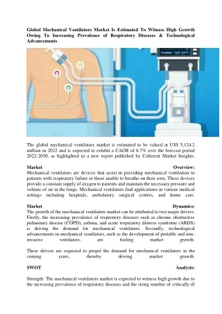
What is a Ventilator? • Ventilator: Flow Generator • A mechanical ventilator is a machine that generates a controlled flow of gas into a patient’s airways. Oxygen and air are received from cylinders or wall outlets, the gas is pressure reduced and blended according to the prescribed inspired oxygen tension (FiO2), accumulated in a receptacle within the machine, and delivered to the patient using one of many available modes of ventilation.
There are two phases in the respiratory cycle, inhalation and exhalation (Total Cycle Time). Gas exchange occurs in both phases. Inhalation serves to replenish alveolar gas. • Inhalation is active • Exhalation is passive (Usually longer) • A complete ventilatory cycle or breath consists of four phases: the initiation of inspiration, inspiration itself, the end of inspiration, and expiration
Rate Determines Total Cycle Time= Ins (sec)+Exp(sec) Exp: Resp Rate 15, Tct is 4 sec (60/15) IE ratio=1:2.7 15:4=.26 or 26% of 4 is my I time .26x4= 1.06 seconds Calculation: Itime:tct-Itime 1.06:4-1.06=2.94 Itime:Itime 1.06: 1.06 IE= 1:2.7
IE Ratio: 1.What is tct if rate is 15? What is I time if E time is 3 seconds? What is IE Ratio? 2. What is tct if rate is 20? What is IE if I time is 40%
If the “I” time is 1 second and the “E” time is 3 seconds , what is the respiratory frequency? • If the respiratory frequency is 20 and the E time is 1.5 seconds, what is the I:E ratio? • What is the I:E if I time is 0.4 seconds and e time is 0.6 seconds? • What is the I:E if the I time ration is 33% or 0.33? • What is the I:E if the I time is 0.6 seconds and the RR is 20 breaths / min?
Mechanical Ventilator (MV) • MVs have four basic functions. • Input power (What turns the Ventilator on) • Electrical, pneumatic, manual • Pneumatic used as a back up, transport, mri • Power transmission and conversion • Control system • Output
Power Transmission and Conversion • Drive mechanism • What Generates the force needed to deliver gas to the patient under pressure • Mechanisms can either be • Gas from a pressure-reducing valve • Driven by an electric motor or compressor • Output control valve • Regulates flow of gas to the patient • A valves controlls output(linear screw valve) • Controls the output waveform
Control Circuit • System that allows the ventilator to manipulate pressure, volume, and flow • May be composed of mechanical, pneumatic, electric, electronic, or fluidic components • Most modern vents combine two or more • May be advantages to components used • MRI: Fluidic controls have no metal and are immune to failure due to electromagnetic interference. They can be electric, pneumatic and fluidic
Control Variables • The primary variable the ventilator controls to cause inspiration • Three possible independent variables • Pressure controlled • Volume controlled • Flow controlled • Elastence and resistance cannot be controlled by Ventilator. • Only one can be controlled; the other two become dependent variables.
Outputs of Gas/Flow Pressure Controller: • Ventilator controls pressure (P), but volume and flow will vary with changes in compliance (C) and resistance (Raw). • Flows and Volumes will change • Volume achieved by set of pressure and I time. • The pressure waveform with be square (constant) during inspiration. • Positive or negative pressure controlled • i.e., an iron lung controls with negative P
Volume and Flow Controllers • Volume controller: • Ventilator controls volume so volume will be constant. • Flow is volume/time, so flow is also constant. • TcT Determined by Rate • IE Ratio is determined by volume, flow, rate • Pressure will vary with changes in C and Raw • Flow controller: (Baby Ventilators) • As above, flow and thus volume constant • Pressure varies with changes in C and Raw • Old neonatal ventilators used flow interruption to deliver volume during inspiration. Fact: Volume is the integral of flow= volume is a part of flow Flow is the derivative of volume= flow comes from volumes
Baseline Variable Before Inspiration start you must know your baseline • Defined by how baseline or end expiratory pressure (EEP) relates to atmospheric pressure • PEEP Positive or supraatmospheric EEP (above 0) • NEEP Negative or subatmospheric EEP (below 0 baseline) • ZEEP Zero EEP equals atmospheric pressure (0 baseline). Normal, used as baseline on Ventilators • To describe what happens during expiration, we must know what baseline variable is in effect.
Initiation of Inspiration • Trigger variable (starts Inspiration) • Machine triggered • Time: determined by rate control • Patient triggered • Pressure • Flow (least work for patient to trigger) • Volume (rare) • Most ventilators provide a manual breath button that the operator activates. • The trigger knob level is often called the sensitivity. • Sensitivity is set to help pt start inspiration
Sensitivity needs to be adjusted for proper ventilation: Pressure: Typically, you set the trigger level 0.5 to 1.5 cm H2O below the baseline expiratory pressure, cause a drop in pressure in circuit. Setting the sensitivity to a higher number, e.g., 3 cm H2O makes the ventilator less sensitive and requires the patient to work harder to initiate inspiration. Conversely, setting the trigger level lower make the ventilator more sensitive and Autotrigger will happen Flow Ventilator-supported breath is initiated when the ventilator detects a drop in flow normally set 1-3L/min below baseline (exp cont. flow 10 trigger set at 2, when flow goes down to 8 breath will start) Remember: Flow in vent circuit is the same and continuous between insp. And exp. Volume: drop in volume (not usually used with adults) Baby Drager vent Remember all Machine Breaths are time trigger
End of Inspiration • Cycle variables terminate inspiratory phase. • Pressure cycledInspiration terminates as preset pressure reached (hit alarm level) • Volume cycledInspiration terminates at preset VT • Flow cycledInspiration terminates when flow drops to a preset value (Pressure Support Ventilation) • Time cycledInspiration terminates when set inspiratory time is reached • Includes any inspiratory holds • Patient cycle: pt must be able to set his own I times and flow.
Inspiration Factor: Limit Variable • Something that limits inspiration but does not terminate the phase • limits are set to make sure all the other variables don’t go out of control in the process of achieving your delivered goal • Pressure limited (volume controlled, time cycle) • Limits the peak inspiratory pressure (PIP) during inspiration • Volume limited (pressure controlled, time cycle) • Limits the amount of tidal volume (VT) delivered during inspiration to set amount • Flow limited (volume controlled, time cycle) • Limits the amount of flow during inspiration
Mr M ventilator recap 1) Control: How the ventilator knows how much flow to deliver • Either Volume Controlled (volume limited, volume targeted) and Pressure VariableorPressure Controlled (pressure limited, pressure targeted) and Volume VariableorDual Controlled (volume targeted (guaranteed) pressure limited) 2) Triggering: what causes the ventilator to cycle to inspiration. Ventilators may be time triggered, pressure triggered or flow triggered. • Time: the ventilator cycles at a set frequency as determined by the controlled rate. • Pressure: the ventilator senses the patient's inspiratory effort by way of a decrease in the baseline pressure. • Flow: modern ventilators deliver a constant flow around the circuit throughout the respiratory cycle (flow-by). A deflection in this flow by patient inspiration, is monitored by the ventilator and it delivers a breath. This mechanism requires less work by the patient than pressure triggering. 3) Cycling: how the ventilator switches from inspiration to expiration: the flow has been delivered to the volume or pressure target - how long does it stay there? • Time cycled - such in in pressure controlled ventilation • Flow cycled - such as in pressure support • Volume cycled - the ventilator cycles to expiration once a set tidal volume has been delivered: this occurs in volume controlled ventilation. If an inspiratory pause is added, then the breath is both volume and time cycled 4) Breaths are either: what causes the ventilator to cycle from inspiration • Mandatory (controlled) - which is determined by the respiratory rate. • Assisted (as in assist control, synchronized intermittent mandatory ventilation, pressure support) • Spontaneous (no additional assistance
5) Flow pattern: constant, accelerating, decelerating or sinusoidal • Sinusoidal = this is the flow pattern seen in spontaneous breathing and CPAP • Decelerating = the flow pattern seen in pressure targeted ventilation: inspiration slows down as alveolar pressure increases (there is a high initial flow). Most intensivists and respiratory therapists use this pattern in volume targeted ventilation also, as it results in a lower peak airway pressure. • Constant = flow continues at a constant rate until the set tidal volume is delivered (square) Rectangular Flow Waveform,HighestPeak Pressure • Accelerating= flow increases progressively as the breath is delivered. This should not be used in clinical practice.
6) Mode or Breath Pattern: there are only a few different modes of ventilation: • CMV = Conventional controlled ventilation, without allowances for spontaneous breathing. Many anesthesia ventilators operate in this way. • Assist-Control = Where assisted breaths are facsimiles of controlled breaths. • Intermittent Mandatory Ventilation = Which mixes controlled breaths and spontaneous breaths. • Simv= Same as IMV but is Synchronized to prevent Breath Stacking • Pressure Support = Where the patient has control over all aspects of his/her breath except the pressure limit.
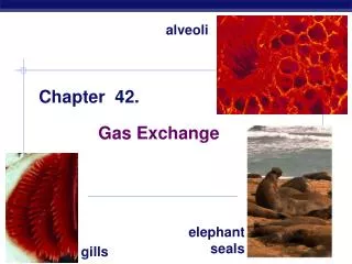
Introduction to Ventilation Five main areas will be considered: Mechanics of ventilation Mechanics of exhalation Work of breathing (WOB) Distribution of ventilation Efficiency and effectiveness of ventilation Ventilation is cyclic: inspiration and expiration Tidal volume (VT): gas moved per phase Facilitates removal of CO2, replenishes O2 Gases move due to pressure gradients Inspiration to expiration
Forces Opposing Lung Inflation Elastic opposition to ventilation Elastic and collagen fibers provide resistance to lung stretch. Application of pressure causes stretch. Greater pressure causes greater stretch until maximum inflation is reached. Deflation is passive recoil and less force is required to maintain same volume. Lung recoil occurs due to tissue elasticity and surface tension Surfactant stabilizes alveoli by preventing collapse Decrease in lung compliance(CL defined as change in volume (ΔV) per change in pressure ) Increase in RAW (airway resistance) normal (0.5 – 2.5 cm H2O/L/sec .
Distribution of Ventilation lung ventilation and perfusion (V/Q) are matched best at bases (dependent area). Apical alveoli are larger but harder to ventilate compared to those at bases. Gravity pulls more blood to bases. In local disease, place good lung down for better V/Q matching. . . . .
Factors Affecting Distribution of Ventilation Thoracic expansion The shape of lungs and muscle action causes greater expansion at bases, so more gas flow Local CL and Raw influence Physiologic deadspace (VDphs) = anatomic (VDanat) + alveolar deadspace (VDalv) VDanat: volume in conducting airways 1 ml/lb of IBW (2.2 ml/kg) is Anatomical vd VDalv: alveoli receive gas but no perfusion or have ventilation that exceeds perfusion VD is the amount gas that does not participate in ventilation: VD/VT= Paco2-Peco2/Paco2 find % multiply by vt to find VA