Download
1 / 18
180 likes | 356 Vues
GaAs radiation imaging detectors with an active layer thickness up to 1 mm. D.L.Budnitsky, O.B.Koretskaya , V.A. Novikov, L.S.Okaevich A.I.Potapov , O.P.Tolbanov , A.V.Tyazhev . Siberian Physical Technical Institute , Russia, Tomsk Fax: +7-3822-233034, E-mail: tyazhev@elefot.tsu.ru. Outline.

E N D
GaAs radiation imaging detectors with an active layer thickness up to 1 mm. D.L.Budnitsky, O.B.Koretskaya , V.A. Novikov, L.S.Okaevich A.I.Potapov , O.P.Tolbanov , A.V.Tyazhev . Siberian Physical Technical Institute , Russia, Tomsk Fax: +7-3822-233034, E-mail: tyazhev@elefot.tsu.ru
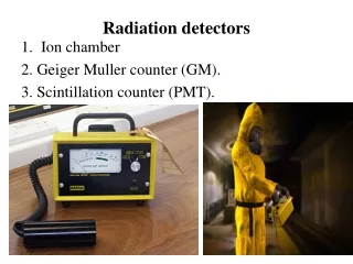
Outline • Introduction • Experimental data Electric field distribution in GaAs detectors based on GaAs:EL2 Resistivity distribution in GaAs:Cr slices Electrophysical characteristics of high resistivity GaAs I-V characteristics of GaAs:Cr CCE dependencies on bias voltage of detectors based on GaAs:Cr • Conclusion
Electric field, kV/cm Electric field, V/m depth, m Distance from p+ contact, m [1] – k. Berwick et al., Proc. Semiconductors for room-temperature radiation detector applications,San Francisco, CA, USA, 12-16 April 1993, MRS Symp. Proc., vol. 302 [2] - A. Cola et al./ Nuc.Instr. And Meth. In Phys. A395 (1997) 98-100 The electric field profile of a LEC SI-GaAs as shown in [1, 2]
Reverse bias: 1- 20V, 2- 40V, 3 - 60V, 4 – 80V 4 3 1 potential, V electric field, kV/cm active thickness, m 2 applied voltage, V depth, m The calculated electric field and electrostatic potential profiles as shown in [2] The active layer thickness has penetration rate 1 m/V
1 – with -radiation 2 - without -radiation U= 300V, 241Am source The amplitude spectrum of the LEC SI-GaAs detector with current oscillations The presence of current oscillations makes difficult the detection of the desired signal in the amplitude spectrum
2 3 4 Ubias 1 I R 890-910 nm 1 – DLM (diffraction lattice monochromator) 2- detector sample, 3 – optical system, 4 – IR-camera (charge-coupled device) Experimental setup for electric field distributionprofiling based on Franz-Keldysh effect.
Electric field strength oscillations in LEC SI-GaAS We have measured samples made in different firms. The analysis of the results shows that in all structures fabricated by means of LEC SI-GaAs technology, a non-uniform (х) distribution and electric field strength oscillations are observed.
GaAs:EL2 t1 t2 t3 d Electric field distribution (1)(EL2 COMPENSATED GaAs LAYERS) Spatial distribution F function and light transmission (T) through detector thickness under bias voltage 250 V in various time instants t1, t2 t3 (t1 t2 < t3) F=1-T
The main disadvantages of the LEC SI-GaAs The low value of the electron life time n(0.2-1 ns). It results in the decrease of the electron drift length and, consequently, in low values of the electron component of the charge collection efficiency. The maximum value of the electric field penetration depth up to 500m that limits the sensitive layer thickness of the LEC SI-GaAs structures and provide non-uniform electric field distribution, (х), through the detector thickness. Current oscillations are formed in the external circuit at a rather low average value of the electric field strength in the detector 1kV/cm. Electric field increase of the capture cross section of EL2+ centers.
absence of current oscillations + EL2 • small value of the electron capture cross section • and absence of the field increase of the capture • cross section on the electric field intensity - Cr • possibility to reach uniform high electric field distribution through whole the detector with the thickness up to 1 mm Advantages of Cr impurity as compared to the EL2 centers for detector material production Deep acceptor Deep donor
Evaporation of Cr n-GaAs Annealing GaAs:Cr with up to 109 *cm Polishing Technological cycle of manufacturing GaAs compensated with Cr
Resistivity distribution in the slice thickness The experimental values of the resistivity are (0.2-1)109cm, which are more than an order higher as compared to the resistivity of structures on the basis of LEC SI-GaAs.
Electrophysical characteristics of high resistivity GaAs The hole concentration in GaAs:Cr exceeds the concentration of electrons. The difference changes from 10 to 100 times depending on conditions of the diffusion process and the initial material characteristics.
Current-voltage characteristics(DIFFUSION CROMIUM COMPENSATED GaAs LAYERS) • High resistivity causes a transformation of the structure of a barrier type to the structures of a resistor type. • The structure current-voltage characteristic is linear. The current density value at operating voltage does not exceed 10-6 A/cm2.
GaAs:Cr 500 V d 1000 V Spatial distribution of the F function and light transmission (T) in detector thicknessd, F=1-T Electric field distribution (2)(DIFFUSION CROMIUM COMPENSATED GaAs LAYERS) The most important distinction of our structures, as compared to the traditional LEC SI-GaAs, is the uniform electric field distribution and the absence of current oscillations.
Amplitude spectra of the GaAs:Cr detectorfor variousenergies of the gamma radiation There is the 70-80 % of CCE in a wide range of gamma-quantum energies (E= 60, 122, 140 keV) for the bias about 600V and the detector thickness of 780m.
Amplitude spectra for GaAs:Cr detectors with differentactive layer thicknesses.E 60 keV (241Am source) It should be noted that value of CCE declines with increase of the detector thickness. Nevertheless, CCE is about 70 % for the detector with an active layer thickness d=1.2 mm when bias voltage is 1000V.
Conclusion • The technology of high temperature Cr doping of n-type GaAs allows to produce the high resistive GaAs layers with resistivity up to 109*cm and thickness up to 1 mm. • The detector structures based on GaAs:Cr have more uniform electric field distribution as compared to the detector structures based on GaAs:EL2 in a wide range of the applied bias voltage. • The detector structures based on GaAs:Cr have applicable values of the CCE in a wide range of the gamma quantum energies (E= 60, 122, 140 keV) and can be used in the production of pixel detector. • We suppose to apply the 3” wafers to produce detector material in the nearest future.